background image

B.


 If there are any missing or damaged pieces or you need assistance with 

assembly please contact the consumer relations department directly.  Call us 

before going back to the store.

STOP

STOP

STOP

STOP

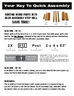
Key Number:

 The first two digits represent the step 

number. The third digit represents the piece. Note 

that if the part is used in multiple steps then the 

number only reflects the first step it is used in.

Quantity

Key Number

Part Description, 

Part Size

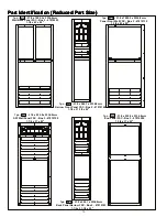
2X  012  Post 2 x 4 x 83”

Step 1: Inventory Parts - Read This Before Starting Assembly

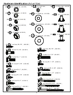
• Please refer to Page 6 for proper hardware assembly.  


•  Each step indicates which bolts and/or screws you will need for assembly, as well as 

any flat washers, lock washers, t-nuts or lock nuts.

A.


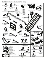
 This is the time for you to inventory all your hardware, wood and accessories, 

referencing the parts identification sheets.  This will assist you with your assembly.


•  The wood pieces will have the key number stamped on the ends of the boards.  

Organize the wood pieces by step, as per the key numbering system below.  

CARTON I.D. STAMP: __  __  __  __  __ 14459 ___ (Box 4)

CARTON I.D. STAMP: __  __  __  __  __ 14459 ___ (Box 5)

CARTON I.D. STAMP: __  __  __  __  __ 14459 ___ (Box 6)

CARTON I.D. STAMP: __  __  __  __  __ 14459 ___ (Box 1)

CARTON I.D. STAMP: __  __  __  __  __ 14459 ___ (Box 2)

CARTON I.D. STAMP: __  __  __  __  __ 14459 ___ (Box 3)

MODEL NUMBER: 

F29055E

TRACKING NUMBER (from ID Plaque):                                        

customersupport@kidkraft.com

Online Parts Replacement:

Cedarsummitplay.com/parts-center-

warranty-claim 

Customer Service: 

1(800) 933-0771 or (972) 385-0100

Europe Customer Service: +31 (0)20 305 8620

europecustomerservice@kidkraft.com 

EU Online Parts Replacement: parts.kidkraft.eu

C.


Read the assembly manual completely, paying special attention to EN71 and 

ASTM warnings; notes; and safety/maintenance information on pages 1 - 6.

D.


Before you discard your cartons fill out the form below.


•  The carton I.D. stamp is located on the end of each carton.  The tracking number is  

located on the Cedar Summit ID Plaque (9320370). 


 •  Please retain this information for future reference.  You will need this information if you 

contact the Consumer Relations Department.

 20 


Summary of Contents for Cedar Summit COPPER RIDGE PLAYSET

Page 1: ...t 110 lbs 49 9 kg per child RESIDENTIAL HOME USE ONLY Not intended for public areas such as multi unit residences schools churches nurseries day cares or parks Warning Only for domestic use WARNING Rev 10 23 2018 Cedar Summit by KidKraft 4630 Olin Road Dallas TX 75244 United States customersupport kidkraft com Online Parts Replacement Cedarsummitplay com parts center warranty claim Customer Servic...

Page 2: ...ose fill surfacing materials washing away during heavy rains D Never add extra length to chain or rope The chains or ropes provided are the maximum length designed for the swinging element s O NOT allow children to play on the play set until the assembly is complete and the unit is properly anchored WARNING e e S t e s y a l p r u o y f o s n o i t a t i m i l y t i c a p a c e v r e s b O front co...

Page 3: ...on the play equipment support posts will help you to see when the material has settled and needs to be raked and or replenished Be sure to rake and evenly redistribute the surfacing in heavily used areas Do not install loose fill surfacing over hard surfaces such as concrete or asphalt Poured In Place Surfaces or Pre Manufactured Rubber Tiles You may be interested in using surfacing other than loo...

Page 4: ...replace deteriorated wood members As with all wood some checking and small cracks in grain is normal Applying a water repellent or stain water based on a yearly basis is important maintenance to maintain maximum life and performance of the product Check the following at the beginning of the play season HARDWARE Inspect for tightness Must be firmly against but not crushing the wood DO NOT OVER TIGH...

Page 5: ...elations department for further assistance warranty service province to province This warranty excludes all consequential damages however some states do not allow the limitation or exclusion of consequential damages and therefore this limitation may not apply to you 10 Year Limited Warranty Cedar Summit by KidKraft warrants that this product is free from defect in materials and workmanship for a p...

Page 6: ... installation liquid soap can be used on all lag type screws For bolts tap T Nut into hole with hammer Insert the hex bolt through lock washer first then flat washer then hole Because the assemblies need to be squared do not completely tighten until instructed Pay close attention to diameter of the bolts 5 16 is slightly larger than 1 4 Note Wafer head bolts with blue lock tight or a bolt with a N...

Page 7: ...with wood parts and look for the Key Number stamped on the end of the wood part see chart below Sort each wood part into the different assembly steps SAVE TIME TIP 2 In addition to the key number stamp you can also identify the wood parts by using the Parts Identification pages in the manual or the Parts Identification weather resistant poster HARDWARE The majority of each hardware part comes pack...

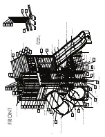
Page 8: ...ide Maze N Wave Slide Bell Telescope w Mount TNR 2 Slide LT Flange TNR 2 Slide RT Flange 9x TNR 2 Slide Elbow TNR 4 Clamp Ring Set 10Pk Flat Panel Bracket Set 4Pk Sign BBQ Lid BBQ Base Sink BBQ Utensils TNR 3 Short Exit TNR 2 Slide Exit Top Door Hardware FRONT Utensil Shelf x2 Fruit Basket Cooktop Door Window Front Roof Panel FSC Narrow Front Panel FSC End Panel FSC Panel Front Wall FSC Panel FSC ...

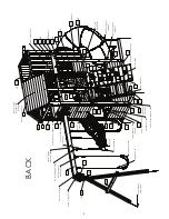
Page 9: ... Swing Rope x4 Spring Loaded Quick Links x6 Acro Handle x2 Acro Bar DX Swing Hanger 6Pk Heavy Flat Bracket x2 KK Playset Plaque Panel Corner Bracket 8Pk Rebar Ground Stake 6Pk EN71 Hand Rail Rocks 18Pk Corner Bracket 9Pk hidden Narrow Angle Bracket 3Pk hidden 2x MOD 5 Pane Window 2Pk TNR Tube Support hidden Acro Rope x2 2x Steel Hand Grips Flat Bracket 2Pk BACK Plastic Formed Washers 18Pk TNR 4 Po...

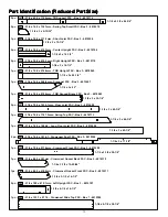
Page 10: ...rowsnest Front Gap FSC Box 3 4819291 5 8 x 4 1 2 x 35 5 8 2pc 261 15 9 x 101 6 x 923 8 Wall Board FSC Box 2 4819313 1pc 451 15 9 x 85 7 x 285 8 mm Bell Top FSC Box 3 4609102 5 8 x 3 3 8 x 11 1 4 1pc 453 15 9 x 85 7 x 285 8 mm Bell Top RT FSC Box 3 4609101 5 8 x 3 3 8 x 11 1 4 1pc 292 15 9 x 82 5 x 971 5 Crowsnest Floor Long Gap FSC Box 3 4819315 5 8 x 3 1 4 x 38 1 4 1pc 295 15 9 x 85 7 x 398 5mm S...

Page 11: ...1086 5mm Table Top FSC Box 2 4819324 15 16 x 4 1 4 x 42 3 4 1pc 121 23 8 x 57 2 x 850 9mm SW Wall Top FSC Box 3 4819071 15 16 x 2 3 8 x 33 1 2 1pc 122 23 8 x 57 2 x 990 6mm Half Wall Top FSC Box 2 4819131 15 16 x 2 1 4 x 39 1pc 123 23 8 x 57 2 x 482 6mm Small Half Wall Top FSC Box 2 4819323 15 16 x 2 3 8 x 19 2pc 325 23 8 x 76 2 x 489mm Wall Tie FSC Box 3 4819117 15 16 x 3 x 19 1 4 1pc 233 23 8 x ...

Page 12: ...ost FSC Box 2 4819316 1 1 4 x 2 1 2 x 33 1 4 2pc 413 31 8 x 60 3 x 340 8mm Roof Tie FSC Box 3 4819260 1 1 4 x 2 3 8 x 13 13 32 2pc 412 31 8 x 60 3 x 170 5mm Short Roof Tie FSC Box 3 4819318 1 1 4 x 2 3 8 x 6 3 4 1pc 051 31 8 x 60 3 x 857 3mm Nest Joist Mid FSC Box 2 4819297 1 1 4 x 2 3 8 x 33 3 4 1pc 054 31 8 x 60 3 x 374 7mm Nest Joist Back FSC Box 3 4819294 1 1 4 x 2 3 8 x 14 3 4 1pc 055 31 8 x ...

Page 13: ...t FSC Box 3 4819110 1 1 4 x 3 x 16 1 2 2pc 324 31 8 x 76 2 x 419 1mm Center Upright FSC Box 2 4819106 1 1 4 x 3 x 16 1 2 1pc 222 31 8 x 79 4 x 971 5mm Crowsnest Front FSC Box 2 4819299 1 1 4 x 3 1 8 x 38 1 4 1pc 227 31 8 x 88 9 x 418 5mm Crowsnest Gusset Front FSC Box 2 4819311 1 1 4 x 3 1 2 x 16 1 2 1pc 228 31 8 x 88 9 x 391mm Crowsnest Gusset Back FSC Box 2 4819310 1 1 4 x 3 1 2 x 15 25 64 1pc 2...

Page 14: ...2 x 39 5 8 2pc 262 31 8 x 128 x 684 3mm Crowsnest Front Spacer FSC Box 2 4819293 1 1 4 x 5 1 32 x 26 15 16 2pc 452 38 1 x 38 1 x 269 9mm Bell Support FSC Box 2 4609100 1 1 2 x 1 1 2 x 10 5 8 1pc 224 31 8 x 139 8 x 971 5 Crowsnest Bottom End FSC Box 3 4819301 1 1 4 x 5 1 2 x 38 1 4 1pc 171 76 2 x 133 4 x 2336 8 Engineered SW Beam FSC Box 1 4819049 3 x 5 1 4 x 92 2pc 183 76 2 x 76 2 x 2336 8mm SW Po...

Page 15: ...Box 2 47819193 1 1 4 x 21 1 2 x 92 1pc 071 31 8 x 939 8 x 2336 8mm SW Wall Panel FSC Box 3 47819150 1 1 4 x 37 x 92 1pc 073 31 8 x 1092 2 x 2336 8mm Wall Back Panel FSC Box 2 47819203 1 1 4 x 43 x 92 1pc 060 31 8 x 939 8 x 2336 8mm End Panel FSC Box 3 47819200 1 1 4 x 37 x 92 Part Identification Reduced Part Size Part Identification Reduced Part Size Part Identification Reduced Part Size Part Iden...

Page 16: ... 4 x 32 1 4 x 45 1pc 311 31 8 x 825 5 x 1143 mm Front Roof Panel FSC Box 3 47609082 1 1 4 x 32 1 2 x 45 1x TNR 2 Slide Lt Flange 3310122 1x TNR 2 Slide Rt Flange 3310123 9x TNR 2 Slide Elbow 3310121 1x TNR 4 Clamp Ring Set 3300130 10 Pk 1x TNR 2 Slide Exit Top 3310124 1x TNR3 Short Exit 3310132 Part Identification Reduced Part Size Part Identification Reduced Part Size Part Identification Reduced ...

Page 17: ...53 2x Heavy Flat Bracket 9200149 1x Corner Panel Bracket 6 Pk 3205977 1x Quick Links w Thread 2pk 3200022 1x BBQ Deluxe Kitchen Set 3330008 1x BBQ Lid 9327812 1x Basket with Fruit 3330015 2x Utensil Shelf 9321691 1x Sign 9331614 1x Bell with Horseshoe 3200309 1x Flat Bracket 2 Pk 3205960 1x BBQ Sink Set 3332608 1x BBQ Utensils 3331610 1x EN71 Hand Rail 3200224 Yellow 1 x D o u b l e R i d e M a z ...

Page 18: ... 1 4 Lock Washer 51303200 66 FW2 5 16 Flat Washer 51103300 52 FW1 1 4 Flat Washer 51103200 34 S8 Pan Screw 12 x 3 4 52433603 12 PB6 Pan Bolt 1 4 x 1 53413210 67 LN1 1 4 Lock Nut 54303200 8 FW6 12 Screw Bezel 9299500 17 PB2 Pan Bolt 1 4 x 1 1 4 53433212 14 FW10 3 8 Flat Washer 51103800 7 LN3 3 8 Lock Nut 54303800 56 PB1 Pan Bolt 1 4 x 3 4 53453203 32 S37 Pan Screw 7 x 5 8 52433009 9 S38 Pan Screw 7...

Page 19: ...Lag 1 4 x 2 1 2 52613222 8 WL3 Wafer Lag 1 4 x 1 3 8 52613216 5 LS9 Lag Screw 5 16 x 4 3 4 52213343 6 WB9 Wafer Bolt 5 16 x 2 1 8 53613324 2 WB8 Wafer Bolt 5 16 x 2 3 8 53613326 7 WB7 Wafer Bolt 5 16 x 3 53613330 6 G21 Hex Bolt 5 16 x 3 3 4 53703333 12 G13 Hex Bolt 5 16 x 6 1 8 53703364 6 WB10 Wafer Bolt 5 16 x 2 5 8 53613329 1 G26 Hex Bolt 3 8 x 9 1 4 53703891 4 G17 Hex Bolt 3 8 x 6 53703860 1 G2...

Page 20: ...ards Organize the wood pieces by step as per the key numbering system below CARTON I D STAMP __ __ __ __ __ 14459 ___ Box 4 CARTON I D STAMP __ __ __ __ __ 14459 ___ Box 5 CARTON I D STAMP __ __ __ __ __ 14459 ___ Box 6 CARTON I D STAMP __ __ __ __ __ 14459 ___ Box 1 CARTON I D STAMP __ __ __ __ __ 14459 ___ Box 2 CARTON I D STAMP __ __ __ __ __ 14459 ___ Box 3 MODEL NUMBER F29055E TRACKING NUMBER...

Page 21: ... the other side with the grooves facing in fig 2 1 B Fit each 022 Tread into grooves on both 020 and 021 Access rails make sure the top edge of the 022 Treads are flush to the front of the Access rails fig 2 1 and 2 2 C Pre drill pilot holes with a 1 8 drill bit and attach rails and treads together using 4 S3 8 x 2 1 2 Wood Screws per tread fig 2 1 16 x 8 x 2 1 2 Wood Screw S3 Fig 2 2 021 020 022 ...

Page 22: ...4 020 022 D Place 023 Ladder Gap on each access rail so there is a 2 3 8 gap between 023 Ladder Gap and the top 022 Tread Attach using 4 S20 8 x 1 3 8 Wood Screws fig 2 3 E Place 024 Rock Rail on the ground next to 020 Right Access so it matches the orientation of the two access rails as shown in fig 2 3 Attach 025 RW AL Support flush to the top of Access Ladder assembly and 024 Rock Rail using 3 ...

Page 23: ...Do not screw boards down yet Rock holes are to be staggered so they do not form a straight line and are at the top of the boards Note Rock Boards are to be flush to 021 Left Access Rail and pilot holes are centred over 024 Rock Rail fig 3 1 B Make sure all boards are tight together and the assembly is square then attach all boards except for 031 Access Board using 4 S20 8 x 1 3 8 Wood Screws per b...

Page 24: ... fig 4 1 and 4 2 C Pre drill pilot holes with a 1 8 drill bit and attach rails and treads together using 4 S3 8 x 2 1 2 Wood Screws per tread fig 4 1 D Place 044 Nest Ladder Gap on each access rail so there is a 2 3 8 gap between 044 Ladder Gap and the top 043 Tread Attach using 4 S20 8 x 1 3 8 Wood Screws fig 4 3 E Center a second 044 Ladder Gap between the bottom 043 Nest Tread and the bottom en...

Page 25: ...ack Wall Tie as shown in fig 5 1 making sure to closely follow the hole orientation Attach using 4 S3 8 x 2 1 2 Wood Screws B Using the next set of pre drilled holes on the 053 Back Wall Tie attach the 054 Nest Joist Back using 2 S3 8 x 2 1 2 Wood Screws fig 5 2 C Place 055 Ladder Side Joist between 051 Nest Joist Mid and 054 Nest Joist Back and attach using 4 S3 8 x 2 1 2 Wood Screws as shown in ...

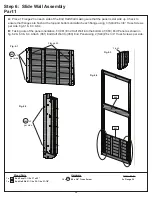
Page 26: ... 1 6 3 6 4 B Taking note of the panel orientation fit 061 End Half Wall into the bottom of 060 End Panel as shown in fig 6 2 6 3 6 4 Attach 061 End Half Wall to 060 End Panel using 2 S40 6 x 3 4 Truss Screws per side Other Parts 2 x Flange 20 Flange 20 Flush S40 per side x 3 S40 per side x 2 Fig 6 1 Fig 6 3 Fig 6 2 Fig 6 4 060 061 Hardware 10 x 6 x 3 4 Truss Screw S40 1 x End Panel 1 1 2 x 37 x 92...

Page 27: ...WL5 1 4 x 2 1 2 Wafer Lags Fig 6 5 6 6 and 6 8 B Place 063 Narrow Front Panel against the right side of 060 End Panel noticing panel orientation The tops and bottoms of the panels should be flush and panels square Pre drill with a 3 16 drill bit then fasten 060 End Panel to 063 Narrow Front Panel with 4 WL5 1 4 x 2 1 2 Wafer Lags Fig 6 5 6 7 and 6 8 Fig 6 6 Fig 6 5 Hardware 8 x 1 4 x 2 1 2 Wafer L...

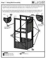
Page 28: ...W Wall Panel with 4 WL5 1 4 x 2 1 2 Wafer Lags fig 7 1 and 7 2 B Place 073 Wall Panel Back against the right side of 071 SW Wall Panel noticing panel orientation The tops and bottoms of the panels should be flush and panels square Pre drill with a 3 16 drill bit then fasten 071 SW Wall Panel to 073 Wall Panel Back with 4 WL5 1 4 x 2 1 2 Wafer Lags fig 7 1 and 7 3 Fig 7 1 Hardware 8 x 1 4 x 2 1 2 W...

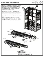
Page 29: ...and are tight together as shown in fig 8 1 B Make sure the assembly is square then on the inside of the assembly tight to 060 End Panel and flush to the bottom of the panels attach 1 081 Floor Joist to 062 Narrow Panel Back and 083 Wall Panel Back and a second 081 Floor Joist to 063 Narrow Front Panel and 072 Panel Front Wall with 4 S7 12 x 2 Pan Screws per board fig 8 1 and 8 2 Swing Wall Assembl...

Page 30: ...8 5 D From inside the assembly insert 3 t nuts into the 073 Wall Back Panel as shown in fig 8 4 then repeat Step C to attach 1 082 Side Joist to 062 Back Panel Narrow and 073 Wall Back Panel fig 8 3 8 4 4 x 8 x 2 1 2 Wood Screw 6 x 5 16 x 2 5 8 Wafer Bolt 5 16 flat washer 5 16 t nut 3 x 5 16 t nut Hardware S3 2 x Side Joist 1 1 2 x 1 1 2 x 63 Wood Parts 082 Fig 8 4 WB10 Fig 8 5 082 Panel 5 8 Step ...

Page 31: ...Bolt with lock washer flat washer and t nut into the inside holes on each side of the assembly In the outside holes loosely install 1 H12 1 4 x 3 Hex Bolt on each side of the assembly These bolts will be tightened in a later step Fig 9 2 C Make sure that assembly is level and install 4 S11 8 x 2 Wood Screws into 052 Front Wall Tie and 053 Back Wall Tie as shown in fig 9 1 and 9 3 10 5 8 15 9mm H10...

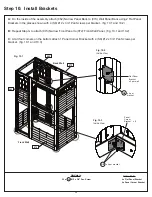
Page 32: ...e assembly attach 062 Narrow Panel Back to 073 Wall Panel Back using 2 Flat Panel Brackets in the places shown with 4 S8 12 x 3 4 Pan Screws per bracket fig 10 1 and 10 2 B Repeat Step G to attach 073 Narrow Front Panel to 072 Front Wall Panel fig 10 1 and 10 2 C At all four corners on the bottom attach 1 Panel Corner Bracket with 4 S8 12 x 3 4 Pan Screws per bracket fig 10 1 and 10 3 063 Front Wa...

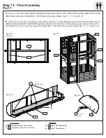
Page 33: ...Board centred over the pilot holes on the 060 End Panel and 071 SW Wall Panel then attach with 2 S4 8 x 3 Wood Screws per panel Attach 111 Floor Board to 112 Long Floor Joist with 2 S20 8 x 1 3 8 Wood Screws per board fig 11 1 11 2 and 11 4 2 x Floor Board 5 8 x 4 1 2 x 35 5 8 1 x Long Floor Joist 1 1 4 x 3 x 63 1 4 12 x 8 x 1 3 8 Wood Screw 4 x 8 x 3 Wood Screw 111 Fig 11 1 Fig 11 2 Top View Fig ...

Page 34: ... then 8 more 111 Floor Boards Make sure all boards are equally spaced then attach to 112 Long Floor Joist and each 082 Side Joist with 6 S20 8 x 1 3 8 Wood Screws per board fig 11 5 11 6 and 11 7 Step 11 Floor Assembly Part 2 Wood Parts 11 x Floor Board 5 8 x 4 1 2 x 35 5 8 1 x Floor Board 5 8 x 3 3 8 x 35 5 8 111 113 Fig 11 5 Slide Wall Swing Wall Hardware 72 x 8 x 1 3 8 Wood Screw S20 Back Wall ...

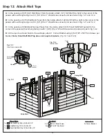
Page 35: ...Top tight to the corner of the panel with overhang facing in with 1 S11 8 x 2 Wood Screw at each end as shown in fig 12 2 D At the top of each slat flush to the wall tops attach 1 Corner Bracket using 3 S37 7 x 5 8 Pan Screws per bracket Note Small Half Wall Top does not require brackets fig 12 1 and 12 3 Hardware Fig 12 1 Fig 12 2 1 x SW Wall Top 15 16 x 2 3 8 x 33 1 2 1 x Half Wall Top 15 16 x 2...

Page 36: ... shown in fig 13 1 Attach using 4 S7 12 x 2 Pan Screws as shown in fig 13 1 B Place Table Top Assembly in the center of opening and tight to 072 Front Wall Panel and attach 131 Table Support to 072 Front Wall Panel with 2 S3 8 x 2 1 2 Wood Screws fig 13 2 and 13 3 132 4 x 12 x 2 Pan Screw 2 x 8 x 2 1 2 Wood Screw S3 S7 131 132 Fig 13 1 Fig 13 2 Fig 13 3 Fig 13 3 072 S7 S3 Flush Flush x 2 Tight Tab...

Page 37: ...assembly attach 132 Table Top to slats in 072 Front Wall Panel with 2 Flat Brackets using 3 S0 8 x 7 8 Truss Screws per bracket fig 13 4 6 x 8 x 7 8 Truss Screw S0 Other Parts 2 x Flat Bracket Fig 13 4 Inside View Table Top Assembly Flat Bracket S0 x 3 per bracket 37 ...

Page 38: ... 141 SW Ground to be flush to the bottom of 071 SW Wall Panel fig 14 1 and 14 2 B Pre drill pilot hole with a 3 16 drill bit then attach 142 Diagonal to 071 SW Wall Panel with 1 WL5 1 4 x 2 1 2 Wafer Lag with flat washer checking that it remains flush to outside edge fig 14 2 C Make sure bottom of 141 SW Ground is flush to bottom of 071 SW Wall Panel then attach with 2 S11 8 x 2 Wood Screws and 1 ...

Page 39: ... x 2 1 8 Wafer Bolts with flat washer and t nut previously installed fig 15 1 and 15 2 Hardware Fig 15 1 3 x 5 16 x 2 1 8 Wafer Bolt 5 16 flat washer Step 15 Attach Access Ladder Rockwall Assembly Part 1 Fig 15 2 18 18 Access Ladder Rockwall Assembly 073 Flush Floor Boards Access Ladder Rockwall Assembly 073 WB9 WB9 WB9 WB9 5 16 T Nut hidden t nut previously installed 5 16 Flat Washer 5 16 Flat Wa...

Page 40: ...st 021 Left Access Rail and 020 Right Access Rail and flush to the top then attach with 4 S20 8 x 1 3 8 Wood Screws fig 15 3 and 15 4 Fig 15 3 Fig 15 4 020 021 4 x 8 x 1 3 8 Wood Screw Flush 031 S20 S20 Step 15 Attach Access Ladder Rockwall Assembly Part 2 40 ...

Page 41: ...drill 1 S7 12 x 2 Pan Screw with flat washer D Center 1 Corner Panel Bracket on each side of 151 Support Diagonal so that each bracket is flat against the brace and the wall panel as shown in fig 15 6 Attach each Corner Panel Bracket using 4 S0 8 x 7 8 Truss Screws Fig 15 5 Fig 15 6 073 1 x 12 x 2 Pan Screw with flat washer 8 x 8 x 7 8 Truss Screw S0 S7 021 20 20 151 071 Flush flat washer 151 Step...

Page 42: ...e edge using 2 S38 7 x 1 1 8 Pan Screws fig 16 1 and 16 2 B On the inside of 161 Door Window Panel measure 22 up from the bottom and attach 1 Door Handle using 2 S37 7 x 5 8 Pan Screws fig 16 1 and 16 2 Inside View 2 x 7 x 1 1 8 Pan Screw 2 x 7 x 5 8 Pan Screw S38 S37 1 x Door Window Panel 1 1 4 x 15 3 4 x 42 1 8 Wood Parts 161 Fig 16 2 Fig 16 1 15 22 161 Door Handle Catch Plate Flush S38 S37 42 ...

Page 43: ... one on the inside Use 2 S37 7 x 5 8 Pan Screws fig 16 3 D Attach 2 Door Hinges on the outside of the 161 Door Window Panel on the opposite side from the Door Handle Judge spacing based on fig 16 3 Use 3 S37 7 x 5 8 Pan Screws per Hinge Note Hinge stops must be tight to 161 Door Window Panel fig 16 4 8 x 7 x 5 8 Pan Screw S37 Other Parts 1 x Door Handle 2 x Door Hinge Top View 161 Door Handle S37 ...

Page 44: ... and a maximum of 5 8 from right side of the opening as shown in fig 16 5 Attach the remaining side of the hinges to 062 Narrow Front Panel using 3 S37 7 x 5 8 Pan Screws per hinge fig 16 5 Fig 16 6 Fig 16 5 6 x 7 x 5 8 Pan Screw S37 3 4 5 8 Step 16 Door Panel Assembly Part 3 063 S37 Door Hinge 44 ...

Page 45: ... On the inside of the assembly attach 162 Door Stop to 063 Narrow Front Panel with 3 S11 8 x 2 Wood Screws making sure 162 Door Stop overhangs 063 Narrow Front Panel by 1 1 4 and is in position to receive the Catch Plate fig 16 8 and 16 9 Fig 16 9 Fig 16 7 1 x Door Stop 1 x 2 1 2 x 10 162 2 x 7 x 1 1 8 Pan Screw 3 x 8 x 2 Wood Screw S38 S11 Other Parts 1 x Magnetic Catch Inside View Side View S38 ...

Page 46: ...6 x 3 Wafer Bolt with flat washer and t nut in the middle bolt hole from the bottom up in 171 Engineered SW Beam as shown in fig 17 1 and 17 4 IT IS IMPORTANT THAT THIS BOLT IS ATTACHED IT WILL MINIMIZE CHECKING OF WOOD D Attach Cedar Summit by KidKraft Plaque to centre of 171 Engineered SW Beam over top of t nut using 4 S38 7 x 1 1 8 Pan Screws fig 17 5 171 Fig 17 3 171 Fig 17 1 Fig 17 2 Fig 17 5...

Page 47: ...72 SW Mount to Heavy Flat Brackets with 2 G21 5 16 x 3 3 4 Hex Bolts with 2 flat washers and 1 lock nut fig 17 9 4 x 5 16 x 3 3 4 Hex Bolt 5 16 flat washer x 2 5 16 lock nut 1 x 3 8 x 6 Hex Bolt 3 8 flat washer x 2 plastic formed washer 3 8 lock nut Other Parts 2 x Heavy Flat Bracket 1 x Heavy L Bracket G21 G17 Wood Parts 1 x SW Mount 3 x 3 x 16 172 G21 5 16 Flat Washer Fort End 5 16 Lock Nut 5 16...

Page 48: ...C Place 181 SW Block Angle and 182 Block SW assembly in between 2 183 SW Post Heavy L Brackets towards the outside Place 1 Heavy C Bracket on the top 183 SW Post and attach with G26 3 8 x 9 1 4 Hex Bolt with 2 flat washers and 1 lock nut as shown in fig 18 4 2 x 3 8 x 6 Hex Bolt 3 8 flat washer x 2 plastic formed washer 3 8 lock nut 1 x 3 8 x 9 1 4 Hex Bolt 3 8 flat washer x 2 3 8 lock nut 6 x 5 1...

Page 49: ... L Bracket fig 18 5 E Attach 171 Engineered SW Beam to Heavy C Bracket with 1 G17 3 8 x 6 Hex Bolt with 2 flat washers plastic formed washer and lock nut fig 18 6 1 x 3 8 x 6 Hex Bolt 3 8 flat washer x 2 plastic formed washer 3 8 lock nut 1 x 3 8 x 4 Hex Bolt 3 8 flat washer x 2 3 8 lock nut G17 Hardware G20 3 8 Flat Washer 3 8 Lock Nut Heavy L Bracket 3 8 Flat Washer Plastic Formed Washer 3 8 Fla...

Page 50: ... 2 Hex Bolt with 2 x flat washer and 1 lock nut in the top hole from inside the assembly fig 18 7 and 18 8 Hardware 5 16 T Nut 5 16 Flat Washer Fig 18 7 171 071 2 x 5 16 x 4 1 2 Hex Bolt 1 5 16 lock washer 5 16 flat washer 5 16 t nut 1 5 16 flat washer x 2 5 16 lock nut G5 172 5 16 Lock Washer 5 16 Lock Nut 5 16 Flat Washer G5 Step 18 Swing Post Assembly Part 3 Flush G5 071 192 171 Flush Fig 18 8 ...

Page 51: ...e on the inside It is important that each side is positioned exactly the same as the diagram fig 19 3 Tighten the lag screw when you are sure 191 Support Cross is level C Attach 1 WB8 5 16 x 2 3 8 Wafer Bolt with flat washer and t nut to 191 Support Cross through the middle hole fig 19 2 and 19 3 IMPORTANT MAKE SURE THE BOLT IS ATTACHED TO MINIMIZE CHECKING OF WOOD Step 19 Attach Cross Support Fig...

Page 52: ...om Step 18 series before installing lag screws A Attach 1 LS9 5 16 x 4 3 4 Lag Screw with flat washer into each 183 SW Post as shown in fig 20 1 B Attach 1 LS9 5 16 x 4 3 4 Lag Screw with flat washer into remaining hole of the Heavy C Bracket into 171 Engineered SW Beam fig 20 1 3 x 5 16 x 4 3 4 Lag Screw 5 16 flat washer 5 16 Flat Washer LS9 Heavy C Bracket LS9 183 LS9 52 ...

Page 53: ...e ground as this could cause the washer to break off fig 21 1 and 21 2 B Attach ground stakes using 1 S7 12 x 2 Pan Screw per ground stake as shown in fig 21 3 C After driving stakes into the ground check for sharp edges caused by the impact of the hammer Smooth any sharp edges from impact area and touch up with outdoor paint Step 21 Install Ground Stakes MOVE FORT TO FINAL LOCATION PRIOR TO STAKI...

Page 54: ...on and hole orientation are correct Attach boards using 2 H12 x 3 Hex Bolts with lock washer flat washer and t nut per board taking care to install the bolts as directed D Fit 225 Barrier Top End into the notches at the top end of the assembly so that it is flush with the sides and the ends of the 221 Crowsnest Posts Attach 225 Barrier Top End using 2 H12 x 3 Hex Bolts with lock washer flat washer...

Page 55: ...t Place 228 Crowsnest Gusset Back tight to 226 Crowsnest Side Joist as shown in fig 22 2 22 4 and secure all 3 parts using 1 G21 5 16 x 3 3 4 Hex Bolt with lock washer flat washer and t nut Step 22 Slide Entrance Assembly Part 2 Wood Parts 2 x Crowsnest Side Joist 1 1 4 x 2 1 2 x 12 1 4 1 x Crowsnest Gusset Front 1 1 4 x 3 1 2 x 16 1 2 1 x Crowsnest Gusset Back 1 1 4 x 3 1 2 x 15 25 64 226 227 228...

Page 56: ...23 2 D Check to make sure the 231 Crowsnest Bottom Side Back is level and install 1 S2 8 x 1 1 2 Wood Screw in the inside bottom hole as shown in Fig 23 1 23 3 Tighten all bolts E Repeat to install 233 Crowsnest Bottom Side Front on the right side of the assembly Fig 23 1 23 3 Step 23 Attach Crowsnest Sides Fig 23 1 Fig 23 2 Fig 23 3 1 x Crowsnest Bottom Side Back 15 16 x 5 1 4 x 35 2 x Wall Board...

Page 57: ...e sure that 226 Crowsnest Side Joists are level with the panel and install 4 S3 8 x 2 1 2 Wood Screws from the inside of the fort as shown in fig 24 1 24 2 D From outside the fort install 2 S3 8 x 2 1 2 Wood Screws into the side of 227 Crowsnest Gusset Front and from inside the fort install 2 S3 8 x 2 1 2 Wood Screws in the pre drilled holes to secure 228 Crowsnest Gusset Back fig 24 1 24 2 Hardwa...

Page 58: ...bly Part 2 E Make sure that slide entrance assembly is square and from outside the assembly install 10 S3 8 x 2 1 2 Wood Screws as shown in fig 24 3 Hardware Hardware S3 S3 10 x 8 x 2 1 2 Wood Screw S3 x1 per side x4 per side Fig 24 3 58 ...

Page 59: ...into the notch in the 060 End Panel Attach 252 Nest Joist Center using 4 S3 8 x 2 1 2 Wood Screws Fig 25 1 25 2 C From underneath the 252 Nest Joist Center and 060 End Panel install 1 S11 8 x 2 Wood Screw so that it s centered under the notches Fig 25 3 8 x 8 x 2 1 2 Wood Screw 1 x 8 x 2 Wood Screw Hardware S3 S11 Step 25 Install Nest Joists Fig 25 1 Fig 25 2 Fig 25 3 251 222 252 060 1 x Short Joi...

Page 60: ... the inside using 2 S20 8 x 1 3 8 Wood Screws per side and attach the bottom of the Wall Board from the outside using 2 S20 8 x 1 3 8 Wood Screws per side Fig 26 1 26 2 26 3 8 x 8 x 1 3 8 Wood Screw Hardware S20 Step 26 Attach Crowsnest Walls Part 1 Fig 26 1 Fig 26 2 Fig 26 3 261 2 x Wall Board 5 8 x 4 x 36 3 8 Wood Parts 261 S20 S20 60 ...

Page 61: ... flush with the 222 Crowsnest Front and the 221 Crowsnest Posts Attach each Crowsnest Front Spacer through the pre drilled holes on the 221 Crowsnest Posts using 3 S4 8 x 3 Wood Screws per side Fig 26 1 26 2 Fig 26 1 Fig 26 2 6 x 8 x 3 Wood Screw Hardware S4 221 2 x Crowsnest Front Spacer 1 1 4 x 5 1 32 x 26 15 16 Wood Parts 262 S4 262 222 x 3 per side 61 ...

Page 62: ... the remaining opening and attach each board using 6 S20 8 x 1 3 8 Wood Screws Fig 27 1 27 2 Hardware Step 27 Install Lower Crowsnest Floor 1 x Crowsnest Front Gap 5 8 x 4 1 2 x 35 5 8 2 x Floor board 5 8 x 4 1 2 x 35 5 8 Wood Parts 271 111 Fig 27 1 Fig 27 2 18 x 8 x 1 3 8 Wood Screw S20 Parts hidden for clarity Parts hidden for clarity 271 271 111 111 S20 x 6 per board 62 ...

Page 63: ...h C Check to ensure that the Nest Ladder is flush with the top of the 111 Floor Board Pre drill using a 1 8 drill bit and attach Nest Ladder using 1 WL5 1 4 x 2 1 2 Wafer Lag with flat washer per side Fig 28 1 28 2 Hardware Step 28 Attach Nest Ladder 051 055 041 055 111 051 only place floor boards to set ladder flush to top only place floor boards to set ladder flush to top 49 2 x Wafer Lag 1 4 x ...

Page 64: ... 3 8 Wood Screws fig 29 2 C Evenly space 2 291 Crowsnest Floor Longs as shown in fig 29 2 and attach using 6 S20 8 x 1 3 8 Wood Screws per board Step 29 Install Upper Floorboards Part 1 Fig 29 1 Fig 29 2 50 111 291 292 Hardware 3 x Floor Board 5 8 x 4 1 2 x 35 5 8 1 x Crowsnest Floor Long Gap 5 8 x 3 1 4 x 38 1 4 2 x Crowsnest Floor Long 5 8 x 4 1 2 x 38 1 4 Wood Parts 111 292 291 34 x 8 x 1 3 8 W...

Page 65: ...4 Nest Joist Back Fig 29 3 E In the remaining opening center and install 295 Short Floor using 4 S20 8 x 1 3 8 Wood Screws Fig 29 3 Step 29 Install Upper Floorboards Part 2 1 x Short Floor Gap 5 8 x 3 3 8 x 15 11 16 1 x Short Floor 5 8 x 3 3 8 x 15 11 16 Wood Parts 294 295 S20 x 4 per board Hardware 8 x 8 x 1 3 8 Wood Screw S20 65 ...

Page 66: ...e 301 2 x 8 x 3 Wood Screw Step 30 Roof Support Assemblies A Attach 1 301 Roof Support to a second 301 Roof Support at peak using 1 S4 8 x 3 Wood Screw Repeat this twice so there are 2 Roof Support Assemblies fig 30 1 S4 S4 Fig 30 1 301 Repeat this step 66 ...

Page 67: ...ews per bracket fig 31 1 B Attach the third Narrow Angle Bracket centred on the middle slat with 2 S0 8 x 7 8 Truss Screws fig 31 2 Step 31 Large Roof Assembly Part 1 S0 1 x Front Roof Panel 1 1 4 x 32 1 2 x 45 1 x Back Roof Panel 1 1 4 x 32 1 4 x 45 Wood Parts 311 312 6 x 8 x 7 8 Truss Screw S0 311 312 Fig 31 1 Fig 31 2 Narrow Angle Bracket Flush Flush Centred Other Parts 3 x Narrow Angle Bracket...

Page 68: ...panels Attach with 8 S11 8 x 2 Wood Screws fig 31 3 D Attach the second Roof Support Assembly on the opposite side making sure that the peaks meet and the ends are flush Attach using 8 S11 8 x 2 Wood Screws fig 31 3 Fig 31 3 Step 31 Large Roof Assembly Part 2 16 x 8 x 2 Wood Screw S11 Roof Support Assembly Roof Support Assembly Flush Flush Flush Flush S11 312 S11 68 ...

Page 69: ...4 lock washer 1 4 flat washer 1 4 t nut A With the notches facing down tap 3 1 4 T nuts into 321 TB Support then fit 323 Left Upright 322 Right Upright and 324 Centre Upright into the notches so the ends and tops are flush taking care to note board orientation Attach with 3 H9 1 4 x 1 1 4 Hex Bolts with lock washer and flat washer fig 32 1 324 322 321 H9 H9 323 324 1 4 T Nut 1 4 Flat Washer 1 4 T ...

Page 70: ...ndow S0 S0 322 325 323 324 321 Other Parts 4 x MOD 5 Pane Window B Place 2 MOD 5 Pane Windows in the openings and attach to 322 Right Upright 323 Left Upright and 324 Centre Upright with 4 S0 8 x 7 8 Truss Screws per window fig 32 2 C Attach 325 Wall Tie flush to the top of 321 TB Support and to 324 Centre Upright with 4 S11 8 x 2 Wood Screws fig 32 3 D Repeat Steps A C for a second Transom Assemb...

Page 71: ...flat washer and t nut fig 33 1 Step 33 Swing Top Assembly Wood Parts 1 x Swing Top 1 1 4 x 3 x 46 3 4 2 x Swing Side Upright 1 1 4 x 2 1 2 x 16 1 2 331 Hardware 2 x 1 4 x 2 1 2 Hex Bolt 1 4 lock washer 1 4 flat washer 1 4 t nut 332 H3 331 1 4 Flat Washer 1 4 Lock Washer 1 4 T Nut H3 332 332 Fig 33 1 71 ...

Page 72: ... in each corner of the 071 SW Wall Panel attach 2 341 Wall Supports to 071 SW Wall Panel with 3 S3 8 x 2 1 2 Wood Screws per support fig 34 1 Fig 34 1 Wood Parts 2 x Wall Support 1 1 2 x 1 1 2 x 55 1 2 341 Hardware 6 x 8 x 2 1 2 Wood Screw S3 Floor Boards 071 341 341 S3 S3 Tight Note hole orientation 72 ...

Page 73: ...lush to the outside of each 341 Wall Support place Swing Top Assembly then attach 341 Wall Supports to 332 Swing Side Uprights with 2 S3 8 x 2 1 2 Wood Screws per support fig 35 1 Hardware 4 x 8 x 2 1 2 Wood Screw Fig 35 1 S3 Swing Top Assembly S3 S3 Flush Flush 332 341 332 071 73 ...

Page 74: ...41 Wall Supports to each Transom Assembly and both the 072 Front Wall Panel and 073 Back Wall Panel with 4 S3 8 x 2 1 2 Wood Screws per support fig 36 2 C From the inside attach each 325 Wall Tie to both 072 Front Wall Panel and 073 Back Wall Panel with 2 S11 8 x 2 Wood Screws per board fig 36 2 Fig 36 1 Hardware 12 x 8 x 2 1 2 Wood Screw 4 x 8 x 2 Wood Screw S3 331 S3 x 2 per Transom Assembly S11...

Page 75: ... Truss Screw per window then attach bottom of windows to 072 Front Wall Panel and 073 Back Wall Panel with 2 S0 8 x 7 8 Truss Screws per window fig 36 3 and 36 4 Hardware 12 x 8 x 7 8 Truss Screw S0 MOD 5 Pane Window MOD 5 Pane Window Fig 36 4 Fig 36 3 321 Front or Back Wall Panel x 3 per window Right or Left Upright S0 75 ...

Page 76: ...alls A Flush to the inside edge of each transom assembly attach 1 371 Swing Top Small using 2 S3 8 x 2 1 2 Wood Screws per side fig 37 1 and 37 2 Fig 37 1 Fig 37 2 Wood Parts 2 x Swing Top Small 1 1 4 x 3 x 5 15 32 371 Flush Flush S3 371 371 371 Transom Assembly Transom Assembly Transom Assembly Hardware 4 x 8 x 2 1 2 Wood Screw S3 76 ...

Page 77: ...h Wall Posts using 2 S4 8 x 2 1 2 Wood Screws per side fig 38 1 B Install 2 S2 8 x 1 1 2 Wood Screw in the inside top hole of 231 Crowsnest Bottom Side Back and 233 Crowsnest Bottom Side Front fig 38 1 Fig 38 1 Wood Parts 2 x Wall Post 1 1 4 x 2 1 2 x 33 1 4 Hardware 4 x 8 x 3 Wood Screw 2 x 8 x 1 1 2 Wood Screw 381 S4 S2 S4 S2 S2 x 2 per post 381 notch fits underneath the Swing Top Smalls 77 ...

Page 78: ...ost as shown in fig 39 1 Attach each 391 Short Wall Tie from the inside using 6 S11 8 x 2 Wood Screws and from the outside using another 2 S11 8 x 2 Wood Screws per side fig 39 1 Step 39 Install Wall Ties Hardware 16 x 8 x 2 Wood Screw S11 Fig 39 1 391 391 381 381 S11 S11 S11 Wood Parts 2 x Short Wall Tie 15 16 x 3 x 17 1 8 391 x 6 per side 78 ...

Page 79: ... edges of 331 Swing Top and the 371 Swing Top Smalls fig 40 1 B Attach 301 Roof Supports to 331 Swing Top and 371 Swing Top Smalls with 1 S3 8 x 2 1 2 Wood Screw per support fig 40 1 and 4 02 C Attach 381 Wall Posts to 301 Roof Supports using 2 S3 8 x 2 1 2 Wood Screws as shown in fig 40 2 Step 40 Attach Large Roof Assembly Hardware 6 x 8 x 2 1 2 Wood Screw S3 Roof Assembly Fig 40 1 Roof Assembly ...

Page 80: ...to 221 Crowsnest Post using 2 S11 8 x 2 Wood Screws fig 41 1 B Repeat to install a second Crowsnest Top Side on the left side of the assembly Step 41 Upper Deck Wall Assembly Part 1 Hardware Fig 41 1 S11 2 x 5 16 x 2 1 8 Wafer Bolt 5 16 flat washer 5 16 Lock Washer 5 16 t nut 4 x 8 x 2 Wood Screw WB9 Wood Parts 2 x Crowsnest Top Side 15 16 x 2 1 2 x 33 3 4 411 411 221 411 381 381 Note holes are to...

Page 81: ...ch the 412 Short Roof Ties to the 301 Roof Supports D Repeat direction in Step C to install a 413 Roof Tie on each side of the roof assembly making sure that the 413 Roof Ties are flush with the top of the 381 Wall Posts and 411 Crowsnest Top Sides Step 41 Upper Deck Wall Assembly Part 2 Hardware S3 Fig 41 2 Fig 41 3 12 x 8 x 2 1 2 Wood Screw Wood Parts 2 x Short Roof Tie 1 1 4 x 2 3 8 x 6 3 4 2 x...

Page 82: ...at the front of the upper crowsnest and attach at the top using 1 H2 x 2 Hex Bolt with lock washer flat washer and t nut and at the bottom using 2 S20 8 x 1 3 8 Wood Screws per board Ensuring they are evenly spaced fig 41 4 Step 41 Upper Deck Wall Assembly Part 3 Hardware Fig 41 4 8 x x 1 1 2 Hex Bolts with flat washer lock washer and t nut 5 x x 2 Hex Bolts with flat washer lock washer and t nut ...

Page 83: ...adder side of 054 Nest Joist Back Do not discard Place 420 Angle Wall A so that the bottom is over the existing holes and the top angle is towards the roof Making sure that the board is straight attach at the bottom using 2 S4 8 x 3 Wood Screws in the existing holes and 1 S11 8 x 2 Wood Screw at the top Fig 42 1 42 2 42 3 B Evenly space 421 Angle Wall B 422 Angle Wall C and 423 Angle Wall D as sho...

Page 84: ...L3 A Place Crow Ladder Grip with one end on the outside of the 041 Nest Right Access and the opposite end on the outside of the 055 Ladder Side Joist Pre drill holes using a 1 8 drill bit then attach using 2 WL3 x 1 3 8 Wafer Lags with flat washer Fig 43 1 43 2 055 041 Crow Ladder Grip 1 4 Flat Washer Fig 43 1 Fig 43 2 84 ...

Page 85: ...p 44 Attach Telescope A On the top right hand corner of the upper crowsnest attach Telescope Base on an angle with 2 S11 8 x 2 Wood Screws fig 44 1 44 2 1 x Telescope 2 x 8 x 2 Wood Screw S11 Fig 44 1 Fig 44 2 Telescope S11 85 ...

Page 86: ...ssembly so they are tight and form a peak then attach to 023 Narrow Front Panel with 1 S3 8 x 2 1 2 Wood Screw and 1 S11 8 x 2 Wood Screw per assembly fig 45 3 Step 45 Install Bell Support Assembly Part 1 Hardware Wood Parts Fig 45 1 Fig 45 3 Fig 45 2 Top View S20 S20 2 x 8 x 2 Wood Screw 6 x 8 x 1 3 8 Wood Screw 2 x 8 x 2 1 2 Wood Screw S11 1 x Bell Top 5 8 x 3 3 8 x 11 1 4 1 x Bell Top RT 5 8 x ...

Page 87: ...per Line through the Bolt Slide Bell under overhang of Horseshoe Mount then insert Bolt up through Bell and Horseshoe Mount then secure with Nut Make sure it is tight fig 45 6 45 7 Fig 45 4 Hardware 4 x 8 x 7 8 Truss Screw S0 Fig 45 5 063 Horseshoe Mount 4X 8 x 7 8 Truss Screw S0 1 x Bell with Horseshoe Mount Other Parts Fig 45 7 4X 8 x 7 8 Truss Fig 45 6 Horseshoe Mount Bell 063 Horseshoe Mount B...

Page 88: ...8 5 16 x 2 3 8 Wafer Bolt with flat washer and t nut fig 46 1 46 2 Fig 46 1 1 x 5 16 x 2 3 8 Wafer Bolt 5 16 flat washer 5 16 t nut WB8 Hardware Other Parts Other Parts 1 x Steering Wheel 071 Fig 46 2 Steering Wheel Steering Wheel WB8 WB8 5 16 Flat Washer 5 16 Flat Washer 5 16 T Nut 88 ...

Page 89: ... there is enough room for BBQ Cooktop and 1 gap to the edge of the wall to the left of BBQ Base Attach BBQ Base to 132 Table Top with 4 S0 8 x 7 8 Truss Screws fig 47 1 47 2 47 3 47 4 B Snap BBQ Lid on to the back of BBQ Base fig 47 2 4 x 8 x 7 8 Truss Screw S0 132 072 BBQ Base Fig 47 1 1 072 132 BBQ Base BBQ Lid BBQ Cooktop Fig 47 2 78 S0 S0 BBQ Lid S0 132 BBQ Base A B Fig 47 4 89 ...

Page 90: ...fig 47 5 47 6 47 7 and 47 8 D Place Faucet and 2 Sink Knobs in opening of Sink and attach Sink Knobs with included hardware fig 47 9 Important Use a hand held screw driver and DO NOT over tighten Hardware Other Parts 1 x BBQ Cooktop 1 x BBQ Sink 4 x 8 x 7 8 Truss Screw S0 BBQ Base S0 BBQ Cooktop Fig 47 5 Fig 47 7 Fig 47 8 Fig 47 9 S0 132 132 BBQ Sink Set BBQ Cooktop BBQ Sink Set Fig 47 6 Faucet Si...

Page 91: ... Sign S0 A From outside the assembly in the top of the opening of 072 Front Wall Panel 1 in from the panel attach 1 Utensil Shelf with 2 S0 8 x 7 8 Truss Screws as shown in fig 48 1 and 48 2 B Attach Sign to the Utensil Shelf fig 48 3 Fig 48 1 Fig 48 2 Fig 48 3 S0 Utensil Shelf Utensil Shelf Sign 1 072 91 ...

Page 92: ... below the BBQ Kitchen attach 1 Utensil Shelf to 131 Table Support with 2 S0 8 x 7 8 Truss Screws as shown in fig 48 4 and 48 5 D Attach Pan Tongs and Spatula to the Utensil Shelf fig 48 6 E Place Basket next to BBQ Kitchen on 132 Table Top fig 48 7 Fig 48 4 Fig 48 5 Fig 48 6 Fig 48 7 072 132 131 S0 Utensil Shelf Utensil Shelf Spatula Pan Tongs S0 Utensil Shelf Centred below the BBQ Kitchen 92 ...

Page 93: ...uble Ride Maze N Wave Slide S7 Note Pre drill all holes using a 1 8 drill bit before installing the pan screws A Place Slide centred in the opening of the 072 Front Wall Panel fig 49 1 B Attach slide to fort using 4 S7 12 x 2 Pan Screws fig 49 2 Fig 49 1 Fig 49 2 Slide 072 S7 93 ...

Page 94: ...icated B Repeat Step A 3 more times to create 4 Elbow Sections in total C Attach TNR2 Slide RT Flange and TNR2 Slide LT Flange together using 4 PB1 1 4 x 3 4 Pan Bolts with lock nut as shown in fig 50 2 This creates the Flange Assembly Hardware 36 x 1 4 x 3 4 Pan Bolt 1 4 lock nut PB1 Other Parts 1 x TNR2 Slide LT Flange 1 x TNR2 Slide RT Flange 8 x TNR2 Slide Elbow Use a 7 16 open end wrench for ...

Page 95: ...ach TNR2 Slide Exit Top and the remaining TNR2 Slide Elbow together using 8 PB1 1 4 x 3 4 Pan Bolts with lock nut as shown in fig 50 4 It is very important to attach bolts as indicated This creates the Exit Elbow Assembly Hardware 8 x 1 4 x 3 4 Pan Bolt 1 4 lock nut PB1 Other Parts 1 x TNR2 Slide Exit Top 1 x TNR2 Slide Elbow TNR2 Slide Elbow TNR2 Slide Exit Top Fig 50 3 Lock Nut PB1 PB1 PB1 Lock ...

Page 96: ...an Screws with 12 Screw Bezel in the pre drilled holes fig 51 1 Make sure the flat surfaces of the Flange Assembly are flush to 222 Crowsnest Front and both sides of 262 Crownest Front Spacer as shown in fig 51 1 51 2 51 3 C Attach the Flange Assembly flush to 222 Crowsnest Front using 4 S6 12 x 1 Pan Screws with 12 Screw Bezel as shown in fig 51 1 and to both 262 Crowsnest Front Spacers using 5 S...

Page 97: ... step A Fit one of the Elbow Assemblies to the Flange Assembly by lining up the arrows on each assembly Attach Elbow Assembly to Flange Assembly using 6 PB1 x 3 4 Pan Bolts and Square Lock Nut fig 52 1 52 2 and 52 3 B Attach one of the Elbow assemblies to another Elbow Assembly making sure to line up the arrows on each assembly Attach 6 x 12 7 mm Pan Bolt with Square Lock Nut Repeat this instructi...

Page 98: ...and working up each side fig 53 2 and 53 3 C At this point make sure all the slide bolts are tight Use a 7 16 open end wrench to hold nut and then tighten bolt with Quadrex Driver Hardware 5 x 1 4 x 3 4 Pan Bolt 1 4 lock nut PB1 Other Parts Exit Elbow Assembly Bottom of Slide Views TNR3 Short Exit Lock Nut PB1 Lock Nut Start with this bolt Slot of TNR3 Short Exit PB1 Fig 53 1 Fig 53 3 PB1 Fig 53 2...

Page 99: ...e arrows are aligned A Fit the Exit End Assembly to the last Elbow Assembly by lining up the arrows on each assembly Notice the elbow orientation fig 54 1 Attach with 6 x 12 7 mm Pan Bolts and Square Lock Nuts fig 54 2 Fig 54 1 Fig 54 2 Square Lock Nut 1 4 x 12 7mm Pan Bolt Elbow Assembly Exit Elbow Assembly 99 ...

Page 100: ...alling Pan Bolts make sure to look at holes so bolts go through the side with the round recess and the lock nuts go through the side with the hexagonal recess Fig 55 3 PB6 Lock Nut After the clamp rings are attached to the elbows fasten them end to end with two pan bolts and lock nuts PB6 Lock Nut Make sure arrows are aligned Fig 55 2 Fig 55 1 Step 55 Attach TNR 4 Clamp Rings TNR4 Clamp Rings TNR4...

Page 101: ...y removed lock nut fig 56 2 C Rotate TNR3 Tube Support and attach to 060 End Panel using 1 S6 12 x 1 Pan Screw as shown in fig 56 2 D Fully tighten screw and bolt 060 Hardware 1 x 12 x 1 Pan Screw 1 x 1 4 x 1 Pan Bolt 1 4 flat washer 1 4 lock nut previously removed PB6 Other Parts 1 x TNR3 Tube Support S6 Step 56 Attach TNR 3 Slide to Fort Remove PB1 1 4 x 3 4 Pan Bolt first then install PB6 1 4 x...

Page 102: ...op hole Make sure both boards are square then attach with 1 S4 8 x 3 Wood Screw fig 57 1 1 x 8 x 3 Wood Screw 1 x 1 4 x 4 1 4 Hex Bolt 1 4 lock washer 1 4 flat washer 1 4 t nut Hardware Wood Parts 1 x TNR Ground Brace 1 1 4 x 3 x 32 1 4 1 x TNR Upright 1 1 4 x 3 x 13 5 32 570 571 1 4 T Nut 1 4 Flat Washer 1 4 Lock Washer 570 H8 S4 S4 Fig 57 1 571 H8 102 ...

Page 103: ...5mm Pan Head Bolt and Square Nylock Nut fig 58 2 D Attach TNR4 Post Mount Base to 571 TNR Upright pre drill with a 1 8 drill bit then attach with 2 S6 12 x 1 Pan Screws fig 58 2 E Attach the Post Mount Clamp to the clamp ring using 1 S37 7 x 5 8 Pan Screw fig 58 2 S11 570 100 TNR4 Post Mount Base TNR4 Post Mount Clamp S37 Square Lock Nut S6 571 x 14 5mm Pan Head Bolt Fig 58 1 Fig 58 2 Fig 58 3 Har...

Page 104: ...s A In the spot shown in fig 59 1 drive 1 Rebar Ground Stake 13 into the ground against the 570 TNR Ground Brace Be careful not to hit the washer while hammering stake into the ground as this could cause the washer to break off B Attach the ground stake to 570 TNR Ground Brace just below the bolt head using 1 S7 12 x 2 Pan Screw as shown in fig 59 1 C After driving stakes into the ground check for...

Page 105: ...tions shown in fig 60 1 attach 1 rock to each rock board using 1 PB2 1 4 x 1 1 4 Pan Bolt with lock washer flat washer and barrel nut and 1 S10 8 x 1 Pan Screw per rock fig 60 1 60 2 The Pan Screw is placed in the hole beneath the Pan Bolt fig 60 2 Note Make sure all hardware is used to secure each rock properly Fig 60 1 Fig 60 2 3 16 Flat Washer 1 4 Barrel Nut S10 PB2 1 4 Lock Washer 105 ...

Page 106: ... 4 Lock Washer Climbing Crater Rock x 2 PB2 2 x Climbing Crater Rock B In the locations shown in fig 60 6 loosely attach Kidney Rocks Rock Johnsons and Crater Rocks with 1 PB2 x 1 1 4 Pan Bolt with lock washer flat washer and barrel nut per rock C Hold each rock in place and mark the hole locations for all remaining bolts Move rocks out of the way and pre drill each marked hole location with a 3 8...

Page 107: ...en attach 2 Steel Hand Grips with 2 WL3 1 4 x 1 3 8 Wafer Lag with flat washer per Steel Hand Grip fig 61 1 61 2 Step 61 Attach Steel Hand Grips to Fort Hardware 4 x 1 4 x 1 3 8 Wafer Lag 1 4 flat washer Other Parts 2 x Steel Hand Grip WL3 Steel Hand Grip 073 025 6 152mm 073 1 4 Flat Washer 1 4 Flat Washer WL3 WL3 Fig 61 1 Fig 61 2 107 ...

Page 108: ...hen attach EN71 Hand Rail using 2 WL3 1 4 x 1 3 8 Wafer Lags with flat washer fig 61 3 61 4 and 61 5 Hardware Fig 61 4 073 021 2 x 1 4 x 1 3 8 Wafer Lag 1 4 flat washer Other Parts 1 x EN71 Hand Rail Step 61 Attach Steel Hand Grips to Fort Part 2 Flush Flush WL3 WL3 WL3 WL3 EN71 Hand Rail Fig 61 3 Fig 61 5 073 A EN71 Hand Rail 1 4 Flat Washer 1 4 Flat Washer 1 4 Flat Washer 108 ...

Page 109: ...wing and acro ropes to the Quick Links attached to the Swing Hangers fig 62 1 Acro Rope EN71 Quick Link Swing Belt Seat Tighten Threaded Link using adjustable wrench Threaded Link attach to Swing and Acro ropes Swing Belt Seat Acro Bar Acro Handles Swing Ropes w crimps Quick Link Acro Rope EN71 European customers receive rope swing instead of chain due to EN71 standards To be installed as per inst...

Page 110: ...tallation over concrete asphalt dirt grass carpet and other hard surfaces creates a risk of serious injury or death from falls to the ground For children 3 to 10 years of age weight limit of 110 lbs per child Maximum number of users Installation Operating Instructions other information is available at www KidKraft com Contact us at KidKraft Dallas TX 75244 USA 1 800 933 0771 Tracking Number Final ...

Page 111: ...NOTES ...

Page 112: ...lent Very Good Average Below Average Poor How would you rate our instructions Excellent Very Good Average Below Average Poor How would you rate the quality of packaging Excellent Very Good Average Below Average Poor Would you recommend the purchase of our products to friends and family Yes No Comments MM DD YY CUT ALONG LINE Fill out your registration card online at www cedarsummitplay com registr...

Reviews: