73
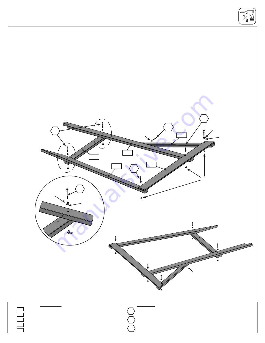
Step 29: Lower Frame Assembly
Part 2
Hardware
H2
3 x
1/4 x 2” Hex Bolt (with 1/4” lock washer, 1/4” flat washer and 1/4” t-nut)
C:
Place 1 (6002) Long Post and 1 (6026) Rock Rail side by side with the (6002) Long Post on the right side,
notched end at the top and facing the inside and the (6026) Rock Rail on the left. Make sure that the angled cut on
the (6026) Rock Rail is at the top, facing inwards towards the (6002) Long Post. (Fig. 29.3 & 29.5)
D:
From the underside of the assembly place 1 (6017) Floor Support making sure the pre-drilled holes match what
is shown on fig.(Fig. 29.3). Attach using 2 (H3) ¼ x 2-1/2” Hex Bolts (with lock washer, flat washer and t-nuts). (Fig.
29.3 & 29.4)
E
: Place 1 (6018) Long Ground across the bottom of both pieces so that it’s flush with the ends of the (6002) Long
Post and the (6026) Rock Rail. Attach (6018) Long Ground using 2 (H2) ¼ x2” Hex Bolts (with lock washer, flat
washer and t-nuts). (Fig. 29.3 )
F:
On the underside of the (6018) Long Ground place 1 (0369) Lower Diagonal tight and flush to the (6002) Long
Post and the (6018) Long Ground. Attach through (6018) Long Ground with 2 (H2) ¼ x 2” Hex Bolts (with lock
washer, flat washer and t-nut). Pre-drill upper hole of (0369) Lower Diagonal with a 1/8” (3.2mm) drill bit and install
1 (LS3) 1/4 x 3” Lag Screw (with flat washer). (fig. 29.3)
Wood Parts
1 x Long Post 31.8 x 82.6 x 1968.5mm
1 x Floor Support 31.8 x 82.6 x 875.3mm
1 x Long Ground 15.9 x 114.3 x 1576.1mm
1 x Rock Rail 31.8 x 69.9 x 1827mm
1 x Lower Diagonal 34.9 x 63.5 x 939.8mm
6018
6026
0369
6017
6002
A
1/4” lock
washer
1/4” lock
washer
1/4” flat
washer
1/4” flat
washer
1/4” flat
washer
H2
H2
H3
H3
LS3
1/4” t-nut
1/4” t-nut
6018
0369
Fig. 29.3
left view
Fig. 29.4
6002
6026
6017
A
H3
LS3
2 x ¼ x2-1/2” Hex Bolts (with lock washer, flat washer and t-nuts)
1 x ¼ x 3” Lag Screw (with flat washer)
right view
Fig. 29.5


