42
Wood Parts
Hardware
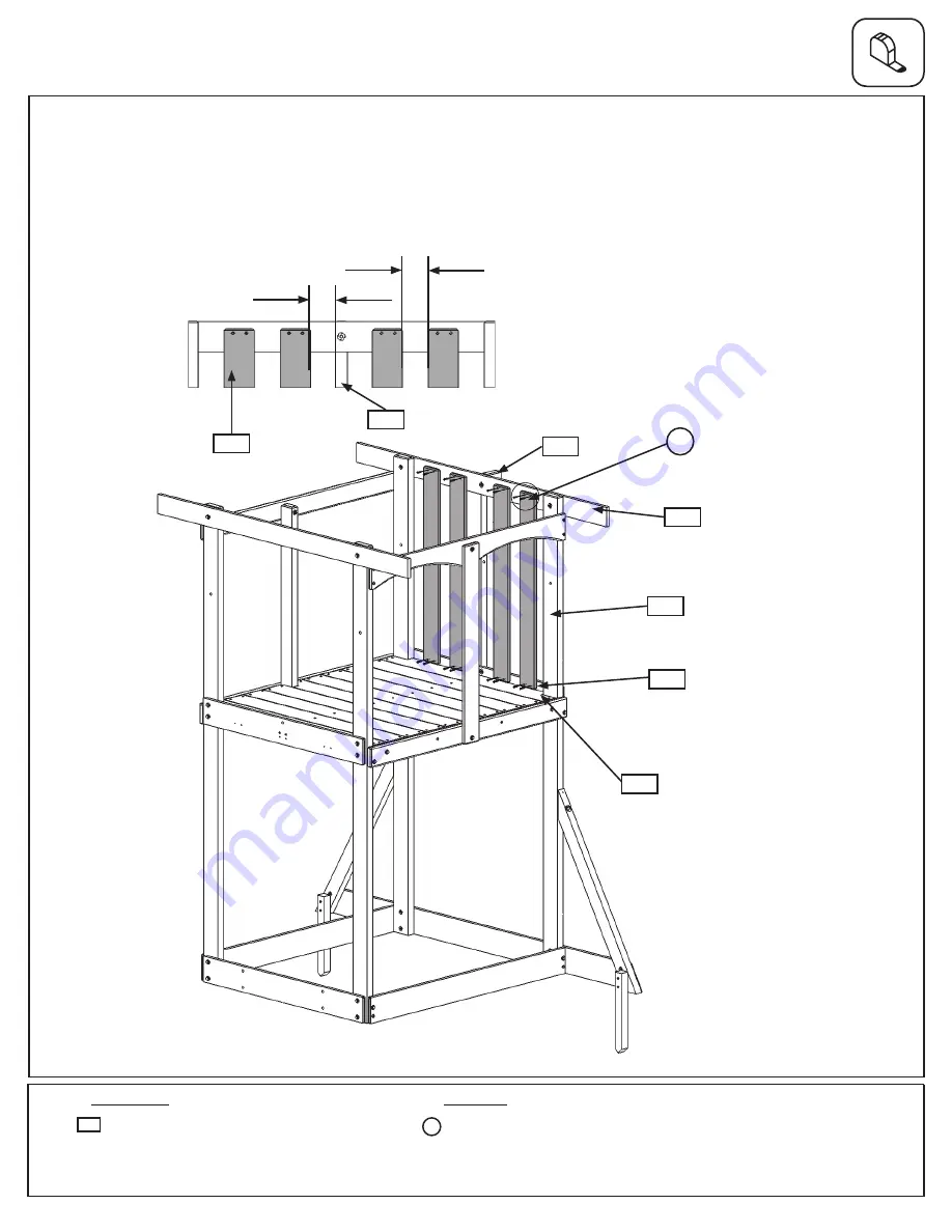
Fig. 19.1
16 x
#8 x 1-1/8” Wood Screw
4 x
CE Wall 1 x 4 x 34”
1846
S1
Step 19: Swing Side Wall Assembly
A:
In between both (1500) Posts on Swing Wall side attach 4 (1846) CE Wall to (1501) Floor End and (1865) SW
Roof Side using 4 (S1) #8 x 1-1/8” Wood Screws per board. Make sure the bottom of the boards are tight against
(1853) Cedar Gap Board. The distance between (1861) SW Mount and (1846) CE Wall should not exceed
2-13/16” and the distance between (1846) CE Walls should not exceed 2-15/16”. (fig. 19.1 and 19.2)
1846
1861
1861
1865
1500
1501
1853
Fig. 19.2
2-13/16”
2-15/16”
S1
x 4 per board


