background image

A

Page 2 / 10

Product Description

DSY/4..32

Datasheet 3.50-32.016-01-EN

Issue 2011-05-04

Important Information Regarding Product Safety

Safety Instructions

This data sheet contains information on installing and commissioning the product "DSY/4..32". Each 
person who carries out work on this product must have read and understood this data sheet. If you 
have any questions that are not resolved by this data sheet, you can obtain further information from 
the supplier or manufacturer.
If the product is not used in accordance with this data sheet, the protection provided will be impaired.
Applicable regulations must be observed when installing and using the device.  Within the EU, these 
include regulations regarding occupational safety and accident prevention as well as those from the 
VDE (Association for Electrical, Electronic & Information Technologies). If the device is used in other 
countries, it is the responsibility of the system installer or operator to comply with local regulations.
Mounting, installation and commissioning work on the devices may only be carried out by qualified 
technicians. Qualified technicians are persons who are familiar with the described product and who 
can assess given tasks and recognize possible dangers due to technical training, knowledge and 
experience as well as knowledge of the appropriate regulations.

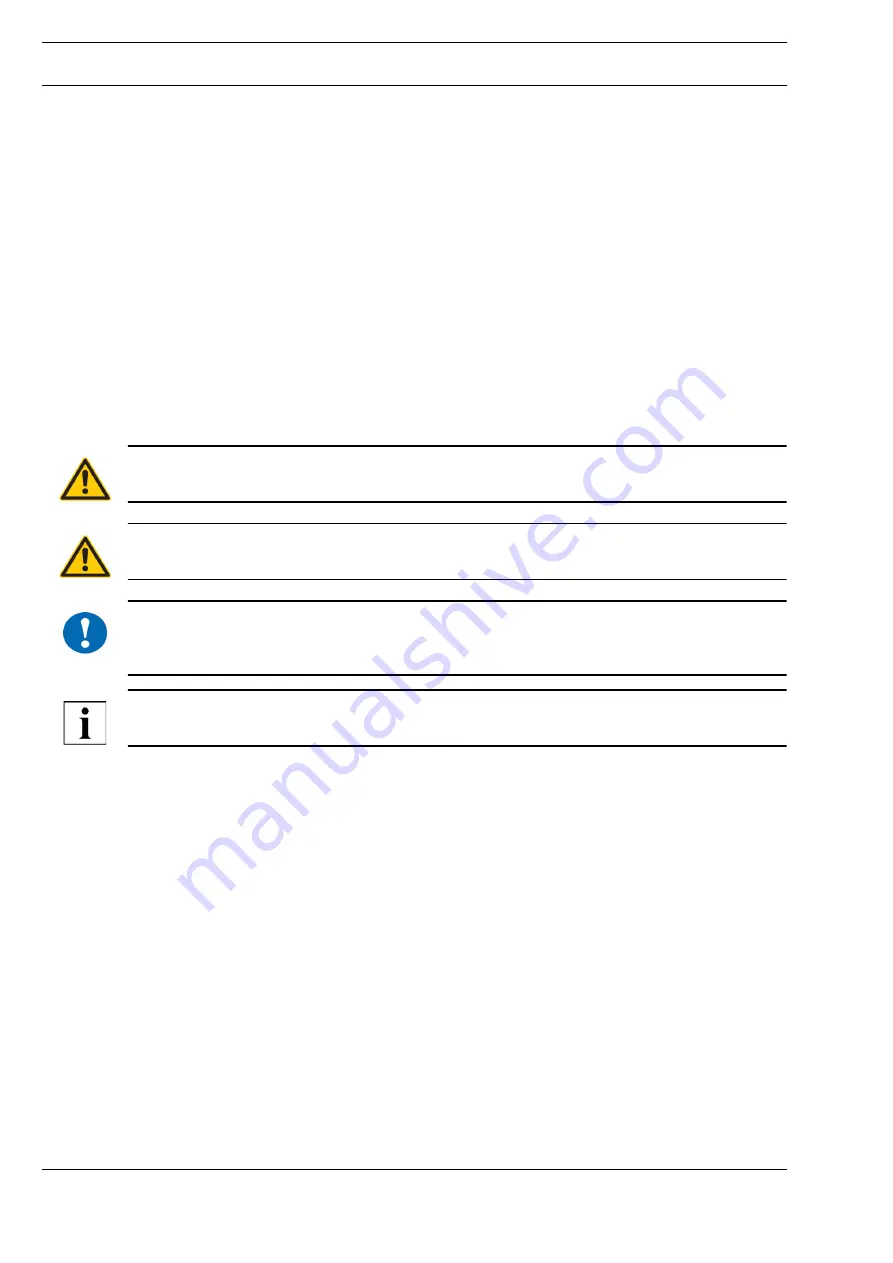
Legend

WARNING

Indicates a hazard of medium risk which can result in death or severe bodily injury if it is not avoided.

CAUTION

Indicates a hazard of low risk which can result in minor or medium bodily injury if it is not avoided.

!

NOTICE

Indicates a hazard of medium risk which can result in material damage or malfunctions if it is not 
avoided.

NOTE

Indicates additional information that can simplify the work with the product for you.

Notes on Disposal

For disposal, the product is considered waste from electrical and electronic equipment (electronic 
waste) and must not be disposed of as household waste. Special treatment for specific components 
may be legally binding or ecologically sensible. The local and currently applicable legislation must be 
observed.

Summary of Contents for DSY/16

Page 1: ...og t fenntartjuk Product Description DSY 4 32 Actuating Drives Application DSY 4 DSY 8 DSY 16 DSY 24 and DSY 32 actuating drives with continuous control are used to control air dampers in VAC systems...

Page 2: ...to comply with local regulations Mounting installation and commissioning work on the devices may only be carried out by qualified technicians Qualified technicians are persons who are familiar with t...

Page 3: ...e area up to 0 8 m 8 Nm for damper surface area up to 2 m 16 Nm for damper surface area up to 4 m 24 Nm for damper surface area up to 6 m 32 Nm for damper surface area up to 8 m Rotational angle 0 to...

Page 4: ...SY 4 DSY 8 32 Additional connection for auxiliary switches AC 230 V 3 1 5 A Contact position at rotational angle of 0 1 2 3 4 24 V AC DC 0 V AC DC 0 10 V DC Y1 0 V DC 0 10 V DC DSY 4 U 1 2 3 4 5 6 24...

Page 5: ...g s electrical system can cause death due to electric shock Mount or remove only when power is switched off Comply with VDE guidelines and local wiring regulations when mounting removing NOTICE Observ...

Page 6: ...cover NOTICE Screws 4 and 8 can be used to reduce the 90 angle working range by 30 each from the two end positions Fig DSY4 1 Cover screw 2 Sliding switch for manual adjustment Actual product not sho...

Page 7: ...uator from power before removing the cover Fig DSY 8 32 1 Cover screw 2 Sliding switch for manual adjustment Actual product not shown 3 Terminal clip for securing the air damper axle 4 Adjuster S Sett...

Page 8: ...n run With the initial ization run both end positions are approached automatically ON position When control signal Y is changed or the rotational angle is automatically limited control signal Y is adj...

Page 9: ...eds to be limited Setting Example Proceed as follows to limit the rotational range to 0 to 60 from 0 to 90 1 Adapter Set actuator to 90 rotational angle for end position Disengage the adapter s retain...

Page 10: ...B Set to 70 rotational angle Move sliding switch for manual adjustment and set adapter to 70 rotational angle Turn ratchet wheel D2 until microswitch E2 switches Replace the cover switch on mains powe...

Reviews: