20
Electricalinstallation
Type 8615500120-000 / 8615500130-000
Warning!
risk of injury from improper installation!
▶
Installation may be carried out by authorized technicians only
and with the appropriate tools!
risk of injury from unintentional activation of the system and
uncontrolled restart!
▶
Secure system against unintentional activation.
▶
Following installation, ensure a controlled restart.
11.2 electrical installation with circular
plug-in connector
procedure:
→
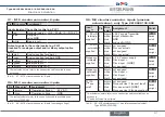
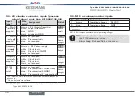
Connect Type 8615500120-000 / 8615500130-000 according
to the tables.
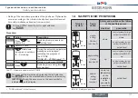
In designs with proximity switch:
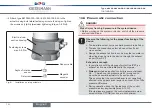
Set the proximity switch (see "11.2.1 Setting the proximity switch
- optional")
When the operating voltage is applied, Type 8615500120-000 /
8615500130-000 is operating.
→
Now make the required basic settings and adjustments for the
positioner/process controller. For description see Chapter
"13 Start-up".
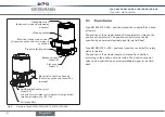
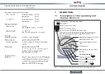
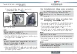
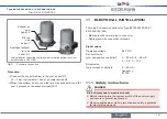
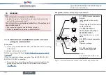
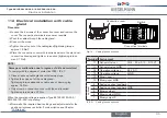
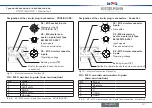
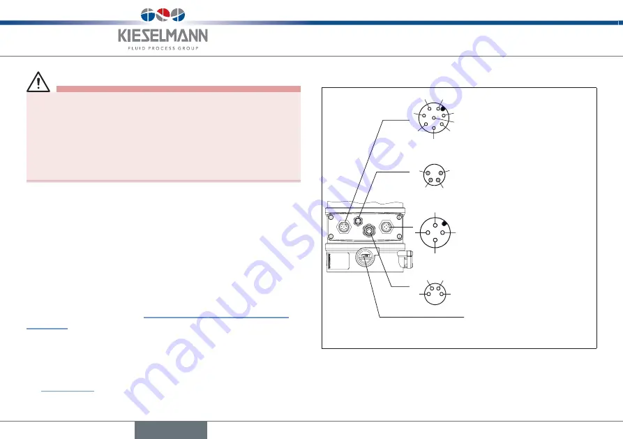
designation of the circular plug-in connectors:
X6 - m12 circular connector,
4-pole
Operating voltage
X1 - m12 circular connector,
8-pole
Input signals for the control
center
Output signals from the control
center (optional)
X4 - m8 socket, 4-pole
Option: proximity switch
Switch
(to operate loosen the screw
connection)
1
2
3
4
5
6
7
8
1
2
3
4
1
2
4
3
1
2
4
3
X5 - m8 circular con-
nector, 4-pole (only type
8615500130-000)
Input signals process actual
value
Fig. 10: Electrical connection with 24 V DC circular plug‑in connector
English
Summary of Contents for 8615500120-000
Page 93: ......
Page 94: ...www kieselmann de...

