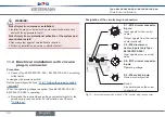
26
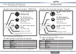
PROFIBUSDP/DeviceNet
Type 8615500120-000 / 8615500130-000
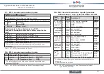
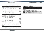
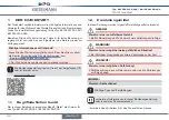
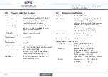
process actual value - Type 8615500130-000
input type
*
terminal assignment
switch
4 ... 20 mA
- internally
supplied
1
2
3
4
+ 24 V transmitter supply
Transmitter output
bridge after GND
GND
Switch
on left
4 ... 20 mA
- externally
supplied
1
2
3
4
not assigned
Process
Process actual -
not assigned
Switch
on right
Frequency
- internally
supplied
1
2
3
4
+ 24 V sensor supply
Clock input +
not assigned
Clock input - (GND)
Switch
on left
Frequency
- externally
supplied
1
2
3
4
not assigned
Clock input +
not assigned
Clock input -
Switch
on right
Pt 100
(
**
see note)
1
2
3
4
not assigned
Process actual 1 (current feed)
Process actual 2 (compensation)
Process actual 3 (GND)
Switch
on right
* Can be adjusted via software
Tab. 7: Process actual value ‑ Type 8615500130‑000
**
For reasons of wire resistance compensation, connect
the Pt 100 sensor via 3 wires.
Always bridge Pin 3 and Pin 4 on the sensor.
12 profiBus dp / deviceneT
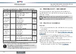
The quickstart guide only describes the electrical installation of
Type 8615500120-000 / 8615500130-000 and the specification
of the basic settings.
The settings for the bus communication via the
BUS.
COMM
menu are described in the operating instructions of
Type 8615500120-000 / 8615500130-000.
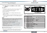
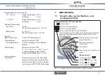
12.1 electrical installation
procedure:
→
Connect Type 8615500120-000 / 8615500130-000 according
to the tables.
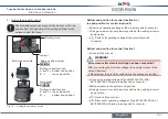
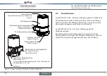
On the electrical connection housing is a setscrew with nut for con-
nection of the technical earth. (see "Fig. 15: Electrical connection
Profibus DP").
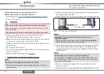
→
Connect setscrew to a suitable grounding point. To ensure
electromagnetic compatibility (EMC), ensure that the cable is as
short as possible (max. 30 cm, Ø 1.5 mm
2
).
When the operating voltage is applied, Type 8615500120-000 /
8615500130-000 is operating.
→
Now make the required basic settings and adjustments for the
positioner/process controller. See Chapter "13 Start-up".
English
Summary of Contents for 8615500120-000
Page 93: ......
Page 94: ...www kieselmann de...

