4-18 Remote Control
PAS SERIES
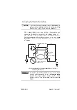
• If multiple units are used under floating conditions and a sin-
gle external contact is used to turn on/off the output, ground
the negative outputside of each power supply unit. Or, use
relays or similar devices for the external contact signal to iso-
late the signal flowing through each unit.
• The insulation of the external contact (S) and the
cable connecting it should be greater than the isola-
tion voltage of the unit. For details on the isolation volt-
age of each model, see Chapter8 "Specifications".
•
When using shielded wires for connection, protect the
uncovered section of the shielded wire by using insu-
lation tubes with a withstand voltage greater than the
isolation voltage of the unit.
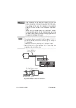
• The release voltage across pins 3 and 2 is approx. 5 V ± 5 % max-
imum, and the short circuit current is approx. 500 µA ± 5 % max-
imum. (The internal circuit is pulled up to 5 V through 10 k
Ω
.)
•
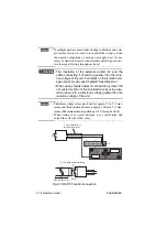
When wiring over a great distance, use a small relay and
extend the coil side of that relay.
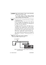
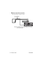
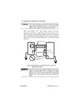
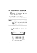
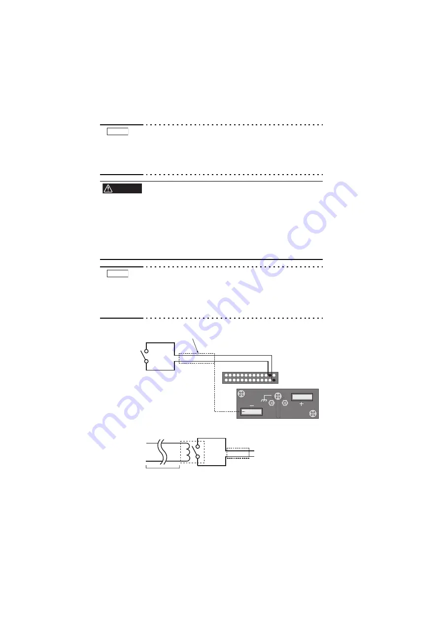
Fig.4-7 ON/OFF control connection
NOTE
WARNING
NOTE
J1
1
3
25
2
13
14
26
2-core shielded or
twisted-pair wire
S
S
For long-distance wiring
Extend this line. Relay
Summary of Contents for PAS 10-105
Page 10: ...VIII PAS SERIES This page has been intentionally left blank ...
Page 54: ...3 22 Basic Operation PAS SERIES This page has been intentionally left blank ...
Page 78: ...4 24 Remote Control PAS SERIES This page has been intentionally left blank ...
Page 131: ...PAS SERIES Specifications 8 13 This page has been intentionally left blank ...
Page 137: ...PAS SERIES Specifications 8 19 This page has been intentionally left blank ...
Page 145: ......

