7-14 Maintenance
PAS SERIES
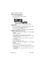
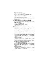
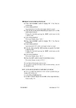
• If you make a mistake in the calibration procedure or connec-
tion and the POWER switch immediately turns OFF when
the OUTPUT is turned on by performing steps 8 through 13,
the OVP calibration value may be off by a great extent.
In such case, repeat steps 3 through 8 or 9 through 13 until
the POWER switch turns off after 30 s to 60 s. (You may
have to repeat the steps tens of times.)
You are done calibrating the OVP.
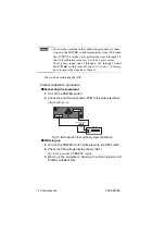
Current calibration procedure
■
Connecting the equipment
1.
2.
Connect a shunt resistor and a DVM to the output terminal.
Shown in Fig.7-16.
Fig.7-16Connection for current system calibration
■
Warming up
3.
Turn on the POWER switch while pressing the SET switch.
4.
Check that the voltage display shows "CAL."
If it is not, press the CURRENT switch.
5.
Warm up the equipment including the shunt resistor and
DVM for sufficient time.
NOTE
DVM
HI
LO
Shunt resistor
Summary of Contents for PAS 10-105
Page 10: ...VIII PAS SERIES This page has been intentionally left blank ...
Page 54: ...3 22 Basic Operation PAS SERIES This page has been intentionally left blank ...
Page 78: ...4 24 Remote Control PAS SERIES This page has been intentionally left blank ...
Page 131: ...PAS SERIES Specifications 8 13 This page has been intentionally left blank ...
Page 137: ...PAS SERIES Specifications 8 19 This page has been intentionally left blank ...
Page 145: ......

