3-2 Basic Operation
PAS SERIES
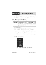
The display that appears when the POWER switch is turned on for the
first time corresponds to factory default settings.
The unit stores the panel settings (excluding OUTPUT ON/OFF con-
dition) immediately before the POWER switch is turned off. The pre-
vious panel settings are used the next time the POWER switch is
turned on.
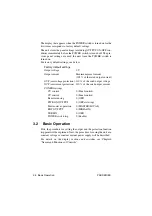
For factory default settings, see below.
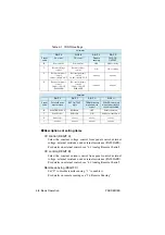
Factory default settings
Output voltage
: 0 V
Output current
: Maximum preset current
(105 % of the rated output current)
OVP (overvoltage protection): 110 % of the rated output voltage
OCP (overcurrent protection) : 110 % of the rated output current
CONFIG settings
CV control
: 0 (Panel control)
CC control
: 0 (Panel control)
Remote sensing
: 0 (OFF)
PWR ON OUTPUT
: 0 (OFF at startup)
Master-slave operation
: 0 (MASTER/LOCAL)
EXT OUTPUT
: 0 (HIGH=ON)
TERMN
: 0 (OFF)
POWER switch trip
: 0 (Enable)
3.2
Basic Operation
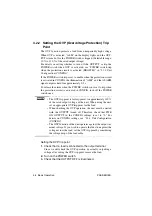
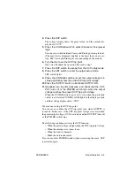
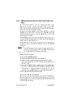
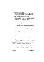
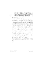
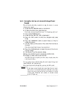
First, the procedure for setting the output and the protection function
trip point will be explained. Next, the procedure for using the unit as a
constant voltage or constant current power supply will be described.
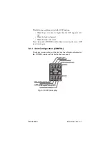
For details on the display sections and switches, see Chapter6
"Names and Functions of Controls".
Summary of Contents for PAS 10-105
Page 10: ...VIII PAS SERIES This page has been intentionally left blank ...
Page 54: ...3 22 Basic Operation PAS SERIES This page has been intentionally left blank ...
Page 78: ...4 24 Remote Control PAS SERIES This page has been intentionally left blank ...
Page 131: ...PAS SERIES Specifications 8 13 This page has been intentionally left blank ...
Page 137: ...PAS SERIES Specifications 8 19 This page has been intentionally left blank ...
Page 145: ......

