3-4 Basic Operation
PAS SERIES
3.2.2 Setting the OVP (Overvoltage Protection) Trip
Point
The OVP function protects a load from unexpectedly high voltage.
When OVP is activated, "ALM" on the display lights, and the OUT-
PUT is turned off or the POWER switch is tripped. (Selectable range:
10 % to 110 % of the rated output voltage)
For details on setting whether to turn off the OUTPUT or trip the
POWER switch when OVP is activated, see "POWER switch trip
when the protection circuit is activated (DEGIT H)" in "3.2.4 Unit
Configuration (CONFIG)".
If the POWER switch trip is set to enable when the protection circuit
is activated in CONFIG, the illumination of "ALM" and the ALARM
signal output is held for approximately 0.5 s.
To release the alarm when the POWER switch is not set to trip when
the protection circuit is activated in CONFIG, turn off the POWER
switch once.
• The OVP trip point is factory-preset to approximately 110 %
of the rated output voltage of the unit. When using the unit,
set an appropriate OVP trip point for the load.
• When checking the OVP operation, the unit must be started
with the OUTPUT turned off. Therefore, check that PWR
ON OUTPUT in the CONFIG settings is set to "0." For
details on CONFIG settings, see "3.2.4 Unit Configuration
(CONFIG)".
• The OVP function of the unit operates against the output ter-
minal voltage. If you wish to operate the function against the
voltage across the load, set the OVP trip point by considering
the voltage drop of the load cable.
Setting the OVP trip point
1.
Check that no load is connected to the output terminal.
Since we will check the OVP operation by actually outputting a
voltage after setting the OVP trip point, remove the load.
2.
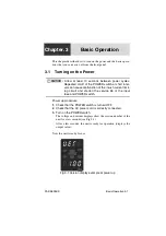
Turn on the POWER switch.
3.
Check that the OUTPUT OFF is illuminated.
NOTE
Summary of Contents for PAS 10-105
Page 10: ...VIII PAS SERIES This page has been intentionally left blank ...
Page 54: ...3 22 Basic Operation PAS SERIES This page has been intentionally left blank ...
Page 78: ...4 24 Remote Control PAS SERIES This page has been intentionally left blank ...
Page 131: ...PAS SERIES Specifications 8 13 This page has been intentionally left blank ...
Page 137: ...PAS SERIES Specifications 8 19 This page has been intentionally left blank ...
Page 145: ......

