PAS SERIES
Basic Operation 3-13
3.3
Connecting the Load
This section describes the load cable used to connect the unit and the
load and the connection to the output terminal.
3.3.1 Load Cable
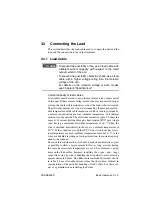
• To prevent the possibility of fire, use a load cable with
sufficient current capacity with respect to the rated
output current of the unit.
• To prevent the possibility of electric shock, use a load
cable with a higher voltage rating than the isolation
voltage of the unit.
For details on the isolation voltage of each model,
see Chapter8 "Specifications".
Current capacity of load cables
Load cables must be rated to carry the maximum rated output current
of the unit. If their current rating exceeds the maximum rated output
current, the cable will remain intact even if the load is short-circuited.
The allowable current of a wire is determined by the maximum allow-
able temperature of the cable insulation, which in turn is governed by
a current-caused resistance loss, ambient temperature, and thermal
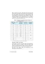
resistance to the outside. The allowable currents in table 3-2 show the
capacity of current flowing through a heat-resistant PVC wire (single
wire) having a maximum allowable temperature of 60 °C when the
wire is stretched horizontally in the air at an ambient temperature of
30 °C. If the condition is such that PVC wires with lower heat-resis-
tant temperature are used, ambient temperature exceeds 30 °C, or the
wires are bundled resulting in low heat radiation, the current capacity
needs to be reduced.
Based on this consideration, it is better to make heat radiation as great
as possible to allow a larger current to flow, as long as wires having
the same heat-resistant temperature are used. For measures against
noise in the load cables, however, installing the + (pos.) and - (neg.)
output lines side by side or bundling them together is more effective
against unwanted noise. The Kikusui-recommended currents shown
in table 3-2 are allowable current values that have been reduced in
consideration of the potential bundling of load cables. Use these val-
ues as a guideline when installing load wires.
WARNING
Summary of Contents for PAS 10-105
Page 10: ...VIII PAS SERIES This page has been intentionally left blank ...
Page 54: ...3 22 Basic Operation PAS SERIES This page has been intentionally left blank ...
Page 78: ...4 24 Remote Control PAS SERIES This page has been intentionally left blank ...
Page 131: ...PAS SERIES Specifications 8 13 This page has been intentionally left blank ...
Page 137: ...PAS SERIES Specifications 8 19 This page has been intentionally left blank ...
Page 145: ......

