PAS SERIES
Basic Operation 3-19
3.5
LOCK Function
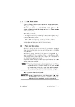
A LOCK switch is provided as a function to prevent inadvertently
changing the settings.
When the panel lock is enabled (LOCK switch lights up), the
switches on the front panel (excluding the OUTPUT switch) and the
dial do not function.
Panel lock procedure
1.
Configure necessary all settings such as the output voltage.
2.
Press the LOCK switch.
The LOCK switch lights up, and the panel lock is enabled.
To clear the panel lock, press the LOCK switch again.
3.6
Remote Sensing
The remote sensing function is used to reduce the influence of voltage
drops due to the load cable resistance and stabilize the output voltage
across the load.
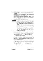
The remote sensing function of this unit can compensate up to
approximately 0.6 V for a single line. Select a load cable with suffi-
cient current capacity so that the voltage drop of the load cable does
not exceed the compensation voltage.
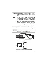
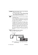
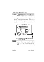
To perform remote sensing, an electrolytic capacitor is required at the
sensing point (load terminal).
• The voltage drop compensation is approximately 0.6 V for a
single line. However, if remote sensing is performed near the
maximum output voltage, the output of the unit is limited by
the maximum voltage (105 % of the rated output voltage).
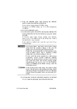
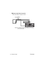
Sensing wire connection procedure
• Never connect wires to the sensing terminals while
the POWER switch is turned on. Such acts can cause
electric shock or damage to the internal circuitry.
NOTE
WARNING
Summary of Contents for PAS 10-105
Page 10: ...VIII PAS SERIES This page has been intentionally left blank ...
Page 54: ...3 22 Basic Operation PAS SERIES This page has been intentionally left blank ...
Page 78: ...4 24 Remote Control PAS SERIES This page has been intentionally left blank ...
Page 131: ...PAS SERIES Specifications 8 13 This page has been intentionally left blank ...
Page 137: ...PAS SERIES Specifications 8 19 This page has been intentionally left blank ...
Page 145: ......

