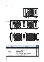
PCR-M
13
No.
Name
Description
Page
+SHIFT
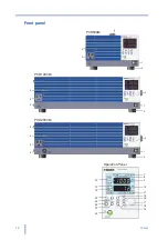
1
POWER
POWER switch. Push ( ) to turn on; push (
) to turn off.
2
Feet
PCR500M: Four locations on the bottom
PCR1000M / PCR2000M: Four locations on the bottom, four locations
on the side.
–
3
OUTPUT outlet
Front panel output
4
Air inlet
Air inlet for internal cooling. A dust filter is built in.
5
Handle
Handle for transporting
–
6
CIRCUIT BREAKER
Reset button of the circuit breaker.
7
Alarm/overload
Illuminates when and alarm or overload occurs.
8
Output mode
The selected mode illuminates (AC, DC, or EXT).
9
Upper numeric display
Displays voltage or frequency.
–
10
Lower numeric display
Displays current or power. Displays the frequency when the memory
is used.
11
Key lock/remote
Illuminates when the key is locked or when in remote mode.
12
Rms value, peak value,
and average value
RMS, PEAK, or AVG illuminates according to the type of value shown
on the numeric display.
13
Memories A, B, and C
The selected memory (A, B, or C) illuminates.
MEMORY illuminates when saving settings and blinks when recalling
settings.
14
Voltage range
The selected voltage range (135 V, 270 V, or AUTO) illuminates.
15
I
Selects the type of value shown on the lower numeric display (RMS,
PEAK, AVG, or W).
RANGE
Sets the voltage range.
16
LIMIT
Sets the limit value. The key illuminates when active.
ALM CLR
Clears alarms.
17
Rotary knob
Changes the settings.
–
18
STORE
Saves to the memory (memories A, B, or C).
KEY LOCK
Locks the keys
19
RECALL
Recalls from memory.
ENTER
Confirms memory recall or storage.
20
OUTPUT
Turns the output on/off.
21
CONFIG
Sets the configuration.
22
LOCAL
Switches to local mode.
SHIFT
SHIFT key
–
23
F
Sets the frequency. The key illuminates when active.
24
V
Sets the voltage. The key illuminates when active.
AC/DC/EXT
Selects the output mode.
See
Summary of Contents for PCR 2000M
Page 34: ...34 PCR M Chapter 2 Installation and Preparation ...
Page 79: ...Appendix ...
Page 91: ...PCR M 91 ...


