background image

22 

PCR-M

Chapter 2  Installation and Preparation

2.3

Precautions to Be Taken When Moving the Product

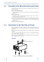
Note  the following points when moving or transporting the product to the


installation location.

Turn off the POWER switch.

Moving the product while the power is turned on can cause electric shock or


damage to it.

Remove all wiring.

Moving the product with the cables connected can cause wires to break or


injuries due to the product falling over.

When transporting the product, be sure to use the original packing materials.

Otherwise, damage may result from vibrations or from the product falling during


transportation.

Be sure to include this manual.

2.4

Attachment to the Rack Mount Frame

Before assemble the unit to the rack mount frame, remove the handle and the feet.


As for the instruction of mount assembly, please refer to the instruction manual of


KRA series.

Install the suitable support angles applying to the used rack system to support the


instrument.

In case the unit is disassembled from the rack mount, it is recommended that all the


removed parts are kept in the storage.

Once the unit is disassembled from the rack mount, please attach all of the removed


parts to original location of each part.

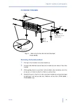
PCR500M

Fig.2-2

Removing the handle and feet (PCR500M)

Cover

Rivet

Handle

Bracket

M4 flat-head screw (M4×0.7×8)

Foot

Screw pin

Summary of Contents for PCR 2000M

Page 1: ...USERʼS MANUAL AC POWER SUPPLY PCR M series Part No IB016983 May 2010 PCR 500M PCR1000M PCR2000M ...

Page 2: ...l computer Please read through and understand the Operation Manual before operating the product After reading always keep the manuals nearby so that you may refer to it as needed When moving the product to another location be sure to bring the manuals as well If you find any incorrectly arranged or missing pages in the manual they will be replaced If the manual gets lost or soiled a new copy can b...

Page 3: ...t here DANGER Indicates an imminently hazardous situation which if ignored will result in death or serious injury WARNING Indicates a potentially hazardous situation which if ignored could result in death or serious injury CAUTION Indicates a potentially hazardous situation which if ignored may result in damage to the product and other property Shows that the act indicated is prohibited Indicates ...

Page 4: ...se of use Never use the product for purposes other than the product s intended use This product is not designed or manufactured for general home or consumer use Input power Use the product within the rated input power voltage range For applying power use the power cord provided For details see the respective page in this manual This product is designed as an equipment of IEC Overvoltage Category I...

Page 5: ...e checking it If a malfunction or abnormality is detected on the product stop using it immediately and remove the power plug from the outlet Make sure the product is not used until it is completely repaired Use cables or wires with sufficiently large current capacity for output wires and load cables Do not disassemble or modify the product If you need to modify the product contact your Kikusui dis...

Page 6: ...em occurs How to read this manual This manual is designed to be read from beginning to end We recommend that you read the manual thoroughly from the beginning before using the PCR M for the first time Intended readers of this manual This manual is intended for users of the PCR M series AC Power Supply or persons teaching other users on how to operate the PCR M series It assumes that the reader has...

Page 7: ...er describes the operations of the PCR M and procedure for controlling the output using external analog signals Chapter4 Remote Control This chapter gives an overview of remote control and describes how to install the instrument driver and software application Chapter5 Maintenance This chapter describes maintenance Conduct periodic maintenance and calibration to maintain the initial performance as...

Page 8: ... which if ignored could result in death or serious injury Indicates a potentially hazardous situation which if ignored may result in damage to the product and other property Indicates information that you should know Explanation of terminology or operation principle Indicates reference to detailed information Indicates menu settings that you select The menu item to the left of the symbol is a high...

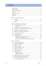
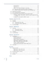
Page 9: ...24 2 6 Connecting the Power Cord 25 2 7 Turning the Power On 28 2 8 Connecting the Load 30 Connecting to the OUTPUT terminal block 30 Connecting to the OUTPUT outlet 32 When the load is located at a distance from the PCR M 33 Chapter 3 Operation 3 1 Switching the Output Mode 36 3 2 Setting the Voltage Range 37 3 3 Setting the Voltage 38 3 4 Setting the Frequency 39 3 5 Turning the OUTPUT On Off 40...

Page 10: ...62 4 2 1 Installing the VISA Library 63 4 2 2 Installing the Software Application 64 4 3 Command Details 64 Chapter 5 Maintenance 5 1 Cleaning 66 5 1 1 Cleaning the Panels 66 5 1 2 Cleaning the Dust Filter 66 5 2 Calibration 68 5 3 Troubleshooting 69 Chapter 6 Specifications 6 1 Specifications 72 Electrical specifications 72 General Specifications 74 RS232C interface specifications 75 GPIB interfa...

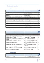
Page 11: ...Frame section 6 2 Dimensions 24 77 Situation Heading page Would like to test drastic changes in voltage or frequency section 3 8 Using Memories 46 Would like to superimpose DC voltage on the AC voltage section 1 2 Options 17 Would like to preset multiple voltages that will be used Saving to the memory 46 Would like to know the load power Display on the lower numeric display 42 Would like to know t...

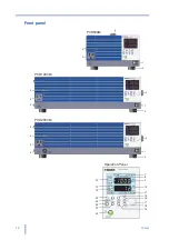
Page 12: ...500M PCR1000M PCR2000M 5 1 2 3 4 1 2 5 3 4 V Hz PEAK Hz 135V 270V RANGE AC DC W A AVG RMS AUTO MEMORY REMOTE ALARM KEY LOCK EXT A B C OVER LOAD 7 14 13 12 8 9 10 11 17 16 15 18 19 20 24 23 22 21 Operation Panel 2 1 2 5 3 2 6 4 ...

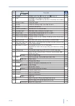
Page 13: ...nd average value RMS PEAK or AVG illuminates according to the type of value shown on the numeric display 42 13 Memories A B and C The selected memory A B or C illuminates MEMORY illuminates when saving settings and blinks when recalling settings 46 14 Voltage range The selected voltage range 135 V 270 V or AUTO illuminates 37 15 I Selects the type of value shown on the lower numeric display RMS PE...

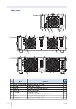
Page 14: ...or cooling 3 RS232C A connector for RS232C remote control 75 4 Option slot Installs an option board 17 5 AC INPUT PCR500M AC inlet PCR1000M PCR2000M AC input terminal block 25 6 AUX A connector for functional expansion 7 Serial number Serial number of PCR M series 1 1 5 2 2 3 4 3 4 5 6 6 7 7 1 5 2 3 4 6 7 PCR500M PCR1000M PCR2000M See ...

Page 15: ...General Description This chapter gives a general description and introduces the features of the PCR M 1 ...

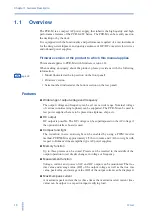
Page 16: ...a wide range Nominal voltage of various countries single phase can be supported The PCR M can be used to test power supplies that are to be placed on airplanes ships etc DC output DC output is possible The DC voltage can be superimposed on the AC voltage if the optional interface board is used Compact and light The reduction in size and weight can be enabled by using a PWM inverter method PCR500M ...

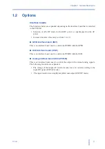
Page 17: ...rface board IB21 This is an interface board used to control the PCR M with the GPIB USB interface board US21 This is an interface board used to control the PCR M with the USB Analog interface board EX04 PCR M This is an interface board used to control the output with external analog signals The following functions are expanded The voltage of the output AC waveform sine wave is varied according to ...

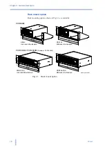
Page 18: ...t option 465 18 31 482 18 98 132 5 5 22 57 2 24 37 75 1 49 KRA3 Inch rack EIA standard 460 480 24 5 100 149 KRA150 Milli rack JIS standard KRB3 TOS Inch rack EIA standard KRB150 TOS Milli rack JIS standard Unit mm inch PCR1000M PCR2000M Example PCR1000M PCR500M 465 18 31 132 5 20 57 2 24 37 5 1 48 460 478 478 18 82 24 5 100 149 ...

Page 19: ...Installation and Preparation This chapter describes the procedures from unpacking to installation 2 ...

Page 20: ...Accessories Power cord The power cord that is provided varies depending on the destination for the product at the factory shipment Ferrite Core Only PCR2000M 1 pc 96 01 0180 85 AA 0004 85 AA 0005 Rated voltage 125 Vac PLUG NEMA5 15 Rated voltage 250 Vac PLUG CEE7 7 85 10 0790 Rated voltage 250 Vac PLUG GB1002 CD ROM 1 pc SA 6021 Cable tie Only PCR2000M 1 pc P4 200 001 or or or 85 10 0630 Power cor...

Page 21: ... indoor use Do not install the product in a corrosive atmosphere Do not install the product in a corrosive atmosphere or in environments containing sulfuric acid mist etc This may cause corrosion of various conductors and bad contacts of connectors inside the power supply leading to malfunction and failure or in the worst case a fire Do not install the product in a dusty location Accumulation of d...

Page 22: ...ns or from the product falling during transportation Be sure to include this manual 2 4 Attachment to the Rack Mount Frame Before assemble the unit to the rack mount frame remove the handle and the feet As for the instruction of mount assembly please refer to the instruction manual of KRA series Install the suitable support angles applying to the used rack system to support the instrument In case ...

Page 23: ...ons and remove the entire handle 3 While pulling down on each foot on the bottom four locations turn the screw pin and remove the foot Remove all four feet 4 Unlatch the pin in the foot on the side four locations using a flat head screwdriver and remove the foot Remove all four feet PCR1000M PCR2000M only Handle Rivet Bracket Cover M4 flat head screw M4x0 7x0 8 Foot Screw pin Foot Rivet Pin Use the...

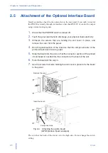
Page 24: ...ding the slot cover in place and remove the cover from the panel 4 Hold the panel section of the board so that the component side of the printed circuit board is facing right 5 Slide the board into the slot so that the connector section of the printed circuit board is inserted into the connector at the back of the slot 6 Push the board all the way in 7 Use the screws that were holding the slot cov...

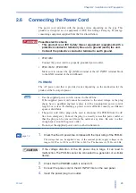
Page 25: ...sed due to the rated voltage or the plug shape have a qualified engineer replace it with an appropriate power cord of length 3 m or less If obtaining a power cord is difficult consult your Kikusui agent or distributor The power cord with a plug can be used to disconnect the PCR M from the AC line in an emergency Connect the plug to an easily accessible power outlet so that the plug can be removed ...

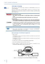
Page 26: ... Make sure the colors of the wires connected to the corresponding input terminals L N and GND are correct Turn off the circuit breaker of switchboard to disconnect the PCR1000M PCR2000M from the AC line in an emergency Circuit breaker of switchboard requirement Rated current PCR1000M 20 A The circuit breaker of which the rated current is more than 20 A is disabled for safety PCR2000M 40 A The circ...

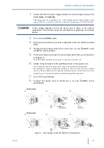
Page 27: ...k 5 Put the terminal cover back to the terminal block that you removed in procedure 3 For PCR1000M use holes on lower side to attach the terminal cover 6 Attach crimp terminals to the switchboard end of the power cord The switchboard end of the input power cable is not provided with terminals For termination attach a crimp style terminal to each wire that meets the terminal screws of the switchboa...

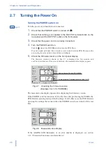
Page 28: ...seconds and a self test is carried out If no error is detected the measured value display appears Fig 2 7 Checking the firmware version Example Ver 1 23 PCR500M The measured value display appears after displaying the firmware version If the POWER switch is turned on for the first time after purchasing the PCR M the PCR M starts up using factory default settings For all other cases the PCR M starts...

Page 29: ... last time Output voltage and frequency settings Output voltage range 135 V 270 V or AUTO Limit value settings Output mode AC DC or EXT Measured value display RMS PEAK AVG or W Locking the Panel Operation Configuration The output on off state is not stored The PCR M always starts up with the output turned off when the power is turned on If the POWER switch is turned off immediately after changing ...

Page 30: ...2 1 please consult with the qualified personnel OUTPUT terminal cover When shipped from the factory the terminal cover is attached using the upper holes so that the OUTPUT terminals are not exposed If you are not using the OUTPUT terminal block attach the terminal cover as shown in Fig 2 10 Fig 2 10 OUTPUT terminal cover Nominal Cross Sectional Area mm2 AWG Reference cross sectional area mm2 Allow...

Page 31: ... is greater than or equal to the diameter of the wires used to connect the load 4 Attach the terminal cover that you removed in procedure 2 using the lower holes It is completed of procedure for PCR500M and PCR1000M As for PCR2000M it is required to attach the ferrite core to the load wire 5 Unlock the ferrite core and open it 6 Close the ferrite core Avoid catching the wire on the ferrite core At...

Page 32: ...reaker when it is over current The maximum rated voltage of the OUTPUT outlet is 125 Vac Maximum output voltage 125 Vac Maximum output current PCR500M 5 Aac PCR1000M PCR2000M 10 Aac Do not connect the load when the maximum rated voltage of the OUTPUT outlet is exceeded or when in DC mode as it can lead to malfunction 1 Turn the POWER switch off 2 Connect the power cord of the load device to the OU...

Page 33: ...al block and the load be sure to turn the POWER switch off and removing the power plug from an outlet or turn off the circuit breaker of switchboard The current rating of the switch must be greater than or equal to the maximum current of the PCR M For the switch circuit use a two pole type switch that cuts off L and N wires simultaneously Be sure to turn the switch off before connecting the load t...

Page 34: ...34 PCR M Chapter 2 Installation and Preparation ...

Page 35: ...Operation This chapter describes the operations of the PCR M and procedure for controlling the output using external analog signals 3 ...

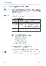
Page 36: ...y SHIFT V to select the output mode The mode switches between AC and DC each time the key is pressed page 57 The mode switches among AC DC EXT AC and EXT DC when the analog interface board is installed The output mode LEDs illuminate according to the mode as shown in Table 3 1 See See Output Mode LEDs That Illuminate Description AC mode AC AC output DC mode DC DC output EXT AC mode AC and EXT Outp...

Page 37: ... OUTPUT off The LED above on the left of the OUTPUT key turns off 2 Press the RANGE key SHIFT I to select the voltage range The range switches among 135 V 270 V and AUTO each time the key is pressed The LED corresponding to the range illuminates If the voltage is set above 137 5 V in the 270 V range or AUTO setting and the range is switched to 135 V the output voltage is set to 0 0 V See V Hz PEAK...

Page 38: ...ecified voltage is shown on the upper numeric display of Fig 3 3 page 37 44 If the OUTPUT is on you can change the set voltage output voltage by turning the rotary knob If the OUTPUT is off you can change the preset voltage by turning the rotary knob The specified voltage is delivered when the OUTPUT is turned on To display the measured value press the V key again The V key turns off and measured ...

Page 39: ...F key The F key illuminates and the frequency setting display appears 2 Turn the rotary knob to set the frequency 40 0 Hz to 500 0 Hz The specified frequency is shown on the upper numeric display of Fig 3 4 Press the F key again then F key light off and the measured value display appears to show the value of measured voltage in the upper numeric display On Off V Hz PEAK Hz 135V 270V RANGE W A AVG ...

Page 40: ...ltage remains at the section connected to the OUTPUT terminal block or OUTPUT outlet even when the OUTPUT is off until the load energy is discharged The discharge time of the internal capacitor when no load is connected is approximately 0 1 seconds To prevent the possibility of electric shock do not touch the OUTPUT terminal block and OUTPUT outlet When the OUTPUT is turned on several volts of und...

Page 41: ...n phase angle is specified in the configuration Because the output capacitor inside the PCR M is discharged when there is no load OUTPUT turns off at the zero crossing phase Fig 3 5 OUTPUT on off phase angle See OUTPUT on Set the OUTPUT on phase angle in configuration OUTPUT off Always turned off at the next zero crossing phase ...

Page 42: ...sured average current AVG Measured power W page 52 The measured peak current indicates the absolute value by measuring the maximum instantaneous value of current The measured peak current is displayed using a positive value even when negative voltage is being output in DC mode The hold time of peak current is set in the configuration The measured current or power is displayed in the lower numeric ...

Page 43: ...o measured value display Other Setting Display Switching Procedure Voltage setting display V key illuminated Press the V key Frequency setting display F key illuminated Press the F key Limit setting display LIMIT key illuminated Press the I key Configuration setting display Memory storage display MEMORY LED illuminated Memory recall display MEMORY LED blinked ...

Page 44: ...y until the desired limit setting is displayed The measured value display is shown after all limit settings are shown 2 Turn the rotary knob to set the condition 3 To set other limit values press the LIMIT key To show another setting display or the measured value display press the V F or I key The voltage setting display frequency setting display or measured value display is shown respectively Fig...

Page 45: ...e frequency outside the limit range Set the limit so that the upper limit is greater than or equal to the lower limit Table 3 10 Selectable range of frequency limit values Output Mode Limit PCR500M PCR1000M PCR2000M AC mode 0 10 A to 5 25 A 0 20 A to 10 50 A 0 40 A to 21 00 A DC mode 0 10 A to 4 2 A 0 20 A to 8 40 A 0 40 A to 16 80 A See Current Limit Operation Display Function TRIP Turns the OUTP...

Page 46: ...y to select the destination memory A B or C The MEMORY LED on the display illuminates Memories A B and C are selected in order each time the STORE key is pressed and the corresponding LED illuminates The upper numeric display indicates the preset voltage In AC mode the lower numeric display indicates the preset frequency 3 Press the ENTER SHIFT RECALL key to store the settings to the memory The se...

Page 47: ...isplay are displayed 2 Press the ENTER SHIFT RECALL key to recall the settings from the memory The settings of the selected memory are recalled and new settings are activated The MEMORY LED on the display turns off To cancel the recall operation press a key other than the RECALL key or ENTER SHIFT RECALL key 3 9 Switching from remote control to local control The RMT LED illuminates when the remote...

Page 48: ... function is activated an alarm A xx or an error E xx occurs as shown Table 3 12 in and the OUTPUT is turned off Alarm Occurs to notify the user that a protection function has been activated Error Occurs on a major operation error or when there is a possibility of malfunction or damage page 51 Table 3 12 Protection function V Hz PEAK Hz 135V 270V RANGE W A AVG RMS AUTO MEMORY REMOTE ALAR A M R KEY...

Page 49: ...SHIFT LIMIT key again the last alarm number is displayed 3 Eliminate the cause of the alarm Refer to Table 3 13 and eliminate the cause of the alarm that occurred according to the description of the displayed alarm number Clearing Errors 1 Check the error number 2 Turn the POWER switch off 3 Eliminate the cause of the error Refer to Table 3 13 and eliminate the cause of the error that occurred acc...

Page 50: ...ed by an inappropriate installation of the PCR M or the ambient temperature being outside the operating temperature specifications 21 74 A 06 Detected less than 8 V of measured voltage against the setting voltage LVP Current limit function TRIP Error E 09 An error is occurring in the internal communication Turn the POWER switch off wait at least 5 seconds and then turn the POWER switch back on E 1...

Page 51: ...ration TRIP If this condition lasts for 3 seconds or longer an alarm A 01 occurs and the output is shut down Current limit operation LIMIT CONTROL software CC operation The preset voltage is controlled internally by the PCR M when an overcurrent condition occurs An alarm does not occur The measured current PEAK is greater than or equal to the maximum peak current If the condition 100 of the maximu...

Page 52: ...the CONFIG key repeatedly until the operating condition you wish to set is displayed The measured value display is shown after all configuration settings are shown 2 Turn the rotary knob to set the condition 3 To set other operating conditions press the CONFIG key To show another setting display or the measured value display press the V F or I key The voltage setting display frequency setting disp...

Page 53: ...Hz Hz W A Communication interface type INTF RS232C baud rate BAUD RS232C XON XOFF control F CTL Phase angle PHAS Communication error trace function TRAC Measured value averaging AVER Peak hold time HOLD OUTPUT on phase ON PH Measured value display 488 uSb On OFF GPIB address ADRS Vendor ID VID Product ID PID V Hz Hz W A V Hz Hz W A V Hz Hz W A 232 ...

Page 54: ...of the peak current Peak hold time SHORT Updates approximately every 0 3 s LONG Holds the peak value for approximately 5 seconds If a greater peak value is measured while holding the new peak value is held for approximately 5 seconds from that point Communication interface The functions of the PCR M can be expanded by installing an interface board to the option slot However the GPIB RS232C and USB...

Page 55: ...ON XOFF control GPIB If you select GPIB select the GPIB address The dipswitches mounted on the IB21 are not used GPIB address 1 to 30 Address USB If you select USB an ID that is required is displayed You cannot change the settings Vendor ID 0x0B3E display Product ID display 0x1009 PCR500M 0x100A PCR1000M 0x100B PCR2000M Error display during remote control Select whether to show or hide the error n...

Page 56: ... V Voltage lower limit 0 0 V Current limit 4 20 A 8 40 A 16 80 A Current limit operation TRIP Locking the Panel Operation Released Configuration OUTPUT on phase OFF Phase angle 0 deg Measured value averaging OFF Peak hold time SHOr SHORT Communication interface type 232 RS232C RS232C baud rate 19 2 19200 bps RS232C XON XOFF control On GPIB address 5 Communication error trace function OFF Memory A ...

Page 57: ...ing to the input DC signal and EXT DC mode in which the input waveform is simplify amplified and output Fig 3 13 EXT AC mode Fig 3 14 EXT DC mode You cannot set the voltage limit when the PCR M is being controlled using external analog signals Accidentally applying an excessive external voltage may damage the load Amplifier Sine wave 10 V Example Input DC voltage 0 V to 10 V Output AC voltage 0 V ...

Page 58: ... V to 10 V 3 Connect an external signal generator to the INPUT terminal 4 Turn the POWER switch on page 36 5 Press the AC DC EXT key SHIFT V to set the OUTPUT mode to EXT AC The EXT and AC LEDs illuminate page 37 6 Press the RANGE key SHIFT I to set the voltage range 135 V or 270 V The LED corresponding to the voltage range illuminates AUTO cannot be selected page 39 7 Press the F key to set the f...

Page 59: ...e lower numeric display shows RMS PEAK and W in order each time the I key is pressed The upper numeric display shows the measured RMS voltage Amplifying the input waveform EXT DC mode The input waveform is simply amplified and output in this mode Turn ATT off Peak value The PCR M outputs a voltage 100 or 200 times the voltage ranging from 1 90 V to 1 90 V Turn ATT on The PCR M outputs voltage rang...

Page 60: ...on TRIP or LIMIT CONTROL Table 3 18 Limit Value of EXT AC mode Fine adjusting the offset You can fine adjust the offset by turning the OFFSET variable resistor using the adjustment screwdriver Adjust the offset so that the output voltage is as close to 0 V DC as possible with the ATT switch turned off and the input terminal shorted Fine adjusting the gain You can fine adjust the gain by turning th...

Page 61: ...Remote Control This chapter gives an overview of remote control and describes how to install the instrument driver and software application 4 ...

Page 62: ...mmands for Programmable Instruments SCPI version 1999 0 Universal Serial Bus Specification Rev 2 0 Universal Serial Bus Test and Measurement Class Specification USBTMC Rev 1 0 Universal Serial Bus Test and Measurement Class Subclass USB488 Specification USBTMC USB488 Rev 1 0 4 2 Installation The accompanying CD ROM contains instrument drivers that can be used with Microsoft Visual Basic Microsoft ...

Page 63: ... is Kikusui s original VISA library that supports VXIplug play VISA Specifications The newest version can be downloaded from Download service of Kikusui website http www kikusui co jp en download KI VISA is not required if NI VISA or Agilent VISA is already installed 1 Load the accompanying CD ROM into the CD ROM drive 2 Move to the VISA folder using the menu program of the CD ROM or Explorer 3 Do...

Page 64: ...enu program of the CD ROM or Explorer 3 Double click ezCtrolPcrmSetup_x_x_xx exe The value for x varies depending on the revision of the application stored on the CD ROM 4 Proceed with the installation according to the instructions on the screen 4 3 Command Details For command details see the Communication Interface Manual on the accompanying CD ROM The communication interface manual is in HTML fo...

Page 65: ...Maintenance This chapter describes maintenance Conduct periodic maintenance and calibration to maintain the initial performance as long as possible 5 ...

Page 66: ...urface erase printed characters cloud the display and so on 5 1 2 Cleaning the Dust Filter A dust filter is installed on the inside of the louver on the front panel Periodically clean the filter to prevent clogging Clogged dust filters hinder the cooling of the inside of the instrument and can cause a malfunction and shortening of the service life 1 Remove the louver A from the panel by placing a ...

Page 67: ...ilter is extremely dirty clean it using a water diluted neutral detergent and dry it completely When the PCR M is in operation air is sucked through the dust filter to cool the inside If moisture is present in the dust filter the temperature or humidity inside the PCR M increases and may cause a malfunction 4 Attach the dust filters to the louver Attach them so that the tab on the louver fits into...

Page 68: ...chment 6 Attach louver A to the panel Slide the entire louver up while holding the 2nd level from the bottom of the louver and fix the pins in place Fig 5 5 Louver A attachment 5 2 Calibration The PCR M is shipped after carrying out appropriate calibrations We recommend periodic calibration to maintain the performance For calibration contact your Kikusui agent or distributor Upper tab 2nd level Lo...

Page 69: ...plug from the outlet PCR500M Turn off the circuit breaker of switchboard PCR1000M PCR2000M Immediately stop the use of the instrument and request repairs Check Item Check Possible Cause Remedy Is the ALARM LED illuminated or an error number displayed Yes An alarm or error occurs Check the alarm or error type section 3 11 Protection Functions and Alarm Errors No Memory error The PCR M has been init...

Page 70: ...ress the LOCAL key to enable local mode Are the voltage limit and frequency limit within the selectable range No The limit values are not set correctly Set the limit values correctly section 3 7 Setting the limit value Check Item Check Possible Cause Remedy Is OVER LOAD illuminated Yes The overload protection tripped The PCR M may be overloaded Check the load No Malfunction Immediately stop the us...

Page 71: ...Specifications This chapter describes the electrical mechanical and optional interface board specifications of the PCR M 6 ...

Page 72: ... or less 36 A 18 A or less Output rating for AC mode Voltage range 135 V 270 V range Rated voltage range 1 V to 135 V 2 V to 270 V Preset voltage range 0 V to 137 5 V 0 to 275 V Voltage setting resolution 0 1 V Voltage setting accuracy 2 1 of set 0 6 V 1 2 V Output phase Single phase Maximum current 3 5 A 2 5 A 10 A 5 A 20 A 10 A Maximum peak current 4 15 A 7 5 A 30 A 15 A 60 A 30 A Load power fac...

Page 73: ... 270 V a load power factor of 1 stepwise change from an output current of 0 A to maximum current or its reverse using the output terminal on the rear panel 10 For an output voltage of 100 V 200 V and a load power factor of 1 Output voltage variation with 55 Hz as reference 11 For 5 Hz to 1 MHz components in DC mode using the output terminal on the rear panel 12 For an output voltage of 100 V 200 V...

Page 74: ...es with the requirements of the following directive and standard Low Voltage Directive 2006 95 EC EN 61010 1 Class I Pollution Degree 2 Circuit system PWM inverter system Environment Operating environment Indoor use Overvoltage Category II Operating temperature and humidity range 0 C to 40 C 32 F to 104 F 20 rh to 80 rh no condensation Storage temperature and humidity range 10 C to 60 C 14 F to 14...

Page 75: ...es Hardware Complies with USB 2 0 Data rate 12 Mbps full speed Program message terminator LF or EOM during reception LF EOM during transmission Device class Complies with the USBTMC USB488 device class specifications PCR M Series Software protocol IEEE Std 488 2 1992 Command language SCPI Specification 1999 0 Operation details Functions expanded during remote control 1 1 There are no specification...

Page 76: ...e DC Frequency characteristics When ATT is OFF 0 3 dB at 500 Hz with respect to 55 Hz typical value Voltage amplification ratio 135 V 270 V range When ATT is OFF 100x 200x Outputs an AC voltage of 0 V to 135 V 0 V to 270 V with respect to a AC voltage input of 0 V to 1 35 V When ATT is ON 19x 38x Outputs a DC voltage of 0 V to 190 V 0 V to 380 V with respect to a DC voltage input of 0 V to 10 V Ot...

Page 77: ...9 MAX 150 9 45 124 4 88 214 8 43 150 5 91 170 6 70 22 0 87 22 0 87 32 1 26 32 1 26 60 2 36 240 9 45 50 1 97 Unit mm inch 4 ø5 0 20 Mounting holes for feet 4 M3 screw holes Max depth 6 mm 0 24 inch Feet M3 screw holes 4 M4 screw holes Max depth 8 mm 0 31 inch 350 13 78 226 8 90 63 2 48 61 2 40 MAX30 1 18 MAX 400 15 75 32 0 26 365 14 37 385 15 16 22 0 87 32 0 26 22 0 87 MAX 20 0 79 128 5 04 MAX 150 ...

Page 78: ...2 76 31 1 22 70 2 76 320 12 60 113 4 45 226 8 90 111 4 37 24 0 94 52 2 05 52 2 05 365 14 37 32 1 26 22 0 86 32 1 26 22 0 86 385 15 16 MAX450 17 72 429 16 89 MAX15 0 59 128 5 03 MAX150 5 91 MAX20 0 79 4 ø5 0 20 Mounting holes for feet 4 M3 screw holes Max depth 6 mm 0 24 inch Feet M4 screw holes 4 M4 screw holes Max depth 8 mm 0 31 inch Unit mm inch ...

Page 79: ...Appendix ...

Page 80: ...rms flows near the peak output voltage as the output current Fig A 2 Fig A 2 Output current waveform In this case the maximum output peak current must not exceed three times the rated maximum current 135 V range Maximum peak current Rated output capacity 100 V 3 270 V range Maximum peak current Rated output capacity 200 V 3 PCR500M PCR1000M PCR2000M Output capacity 500 VA 1000 VA 2000 VA 0 0 1 2 3...

Page 81: ...n voltage is applied to a motor or lamp load an inrush current of several to several tens of times the normal current may flow for several tens to hundreds of cycles For capacitor input rectifying loads For electronics devices with a capacitor input type rectifier circuit at the input if a protective limiting circuit against an inrush current is not provided an inrush current several tens to hundr...

Page 82: ...mum current If the current limiting function is activated OVER LOAD illuminates and the output voltage gradually drops If this condition lasts approximately 3 seconds the output is automatically turned off Peak current and power monitor functions This function is activated if the PCR M s peak current exceeds three times the rated maximum current If a current exceeding three times the rated maximum...

Page 83: ...ge the setting If the rated maximum current is exceeded reduce the load Sudden output current increase If the output voltage waveform is distorted as shown in Fig A 4 b 1 b 2 or c the internal protection function is activated Overload Condition Remedy Output current increase If the voltage drops as shown in Fig A 4 a the current limiting function is activated If the current limit value is set chan...

Page 84: ...interface For details on the commands see the Communication Interface Manual Fig A 5 Waveform example Voltage waveform Normal operation When the current limit function is activated a Voltage waveform Voltage waveform Normal operation When the internal protection function is activated Normal operation When the internal protection function is activated b 1 b 2 Current waveform Voltage waveform c AC ...

Page 85: ...Hz in AC mode or when the output voltage is 100 V for the 135 V range or 200 V for the 270 V range in DC mode The maximum current in DC mode is 80 of that of AC mode Rated output current For AC mode The maximum continuous value of the output current rms value that has been reduced by the output voltage For DC mode The maximum continuous value of the output current unit A that has been reduced by t...

Page 86: ...r factor is 1 Output voltage response time The time unit μs for the output voltage change to exceed 10 of the overall change and return within 10 of the overall change when the output current percentage is changed from 0 to 100 given that the output voltage is 100 V for the 135 V range or 200 V for the 270 V range and the load power factor is 1 in the AC mode Fig A 7 Output voltage response time C...

Page 87: ...ce between the AC voltage and AC current Form factor The form factor is the ratio of the rms value with respect to the average value Crest factor CF The crest factor is the ratio of the rms value with respect to the peak value crest value of the waveform The crest factor is 1 41 for sine waves Power factor Active power Apparent power Form factor Rms value Average value Crest factor Peak value Rms ...

Page 88: ...two to three times the rms value and the flow angle current flow period is 20 deg to 90 deg centering on the output voltage peak phase angle 90 deg or 270 deg Fig A 8 Capacitor input type rectifying circuit load Examples of major capacitor input type rectifying loads Household electric appliances TV sets video equipment such as VCRs audio equipment microwave ovens inverter air conditioners and inv...

Page 89: ...ite Core 31 firmware version 16 Form factor 87 frequency limit values selectable range of 45 G GPIB address 55 GPIB interface board 17 I initialization 56 interface board attachment of 24 L LIMIT CONTROL 45 51 limit value 44 loads that draw an inrush current 81 loads that generate surges 81 lock releasing of 48 louver A removal 66 louver attachment 68 Louver B removal 67 lower numeric display 42 M...

Page 90: ... maximum current 85 rated output power capacity 85 rated output current 85 remote control 54 RS232C baud rate 55 RS232C XON XOFF control 55 S storage humidity range 21 storage temperature range 21 T transformer load 81 transformers and slide transformers 81 TRIP 45 51 troubleshooting 69 U USB interface board 17 V vendor ID 55 VISA driver 63 voltage limit values selectable range of 45 ...

Page 91: ...PCR M 91 ...
Page 92: ...AC POWER SUPPLY PCR M SERIES USER S MANUAL ...

Reviews: