2 PD05M-PCR-LE/PD05S-PCR-LE
Setting the Addresses
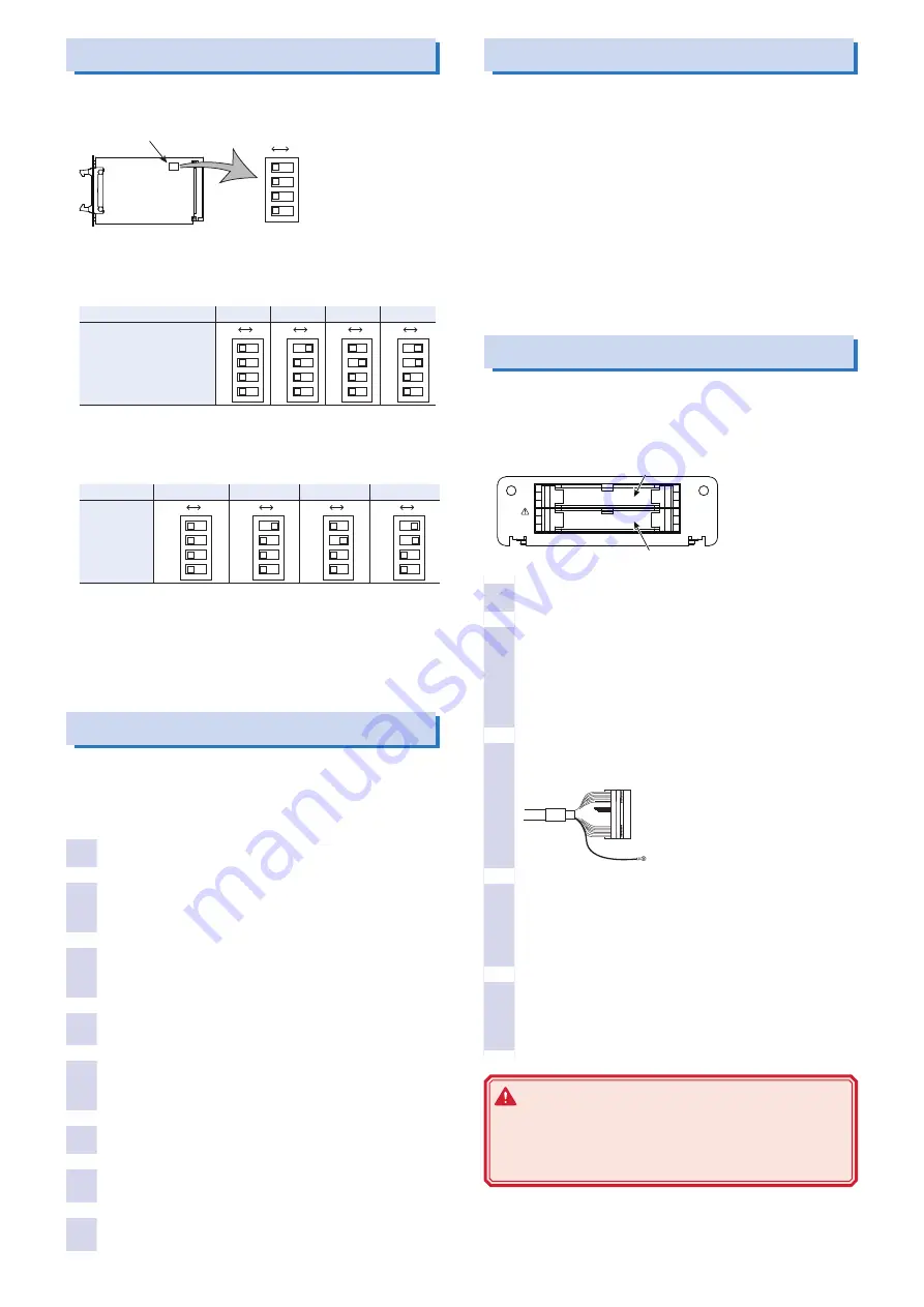
First, set the PD05M-PCR-LE and PD05S-PCR-LE addresses. Use
the dip switches on the boards to set the addresses.
OFF
ON
1
2
3
4
Setting of the DIP switches
Location of DIP switches
(Part-mounted face)
Factory default
PD05M-PCR-LE: 2unit
PD05S-PCR-LE: slave1
• Setting the address of Master (PD05M-PCR-LE)
The master unit address varies depending on the number of units
in parallel operation.
Number of PCR-LE in parallel
2 Units
3 Units
4 Units
5 Units
DIP-Switch Settings
OFF
ON
1
2
3
4
OFF
ON
1
2
3
4
OFF
ON
1
2
3
4
OFF
ON
1
2
3
4
• Setting the address of slave (PD05S-PCR-LE)
The slave numbers have no bearing on the placement of the power
supplies.
Slave1
Slave2
Slave3
Slave4
DIP-Switch
Settings
OFF
ON
1
2
3
4
OFF
ON
1
2
3
4
OFF
ON
1
2
3
4
OFF
ON
1
2
3
4
• Configuration example for parallel operation of three units (in-
cluding the master unit)
Configure PD05M-PCR-LE for three units. Set the first PD05S-
PCR-LE to slave 1 (factory default setting) and the second
PD05S-PCR-LE to slave 2.
Installing the board on the PCR-LE
The PCR-LE that has the PD05M-PCR-LE installed is the master unit;
the PCR-LEs that have the PD05S-PCR-LEs installed are the slave
units. When performing parallel operation using different PCR-LE Se-
ries models, set the model with the largest capacity to the master unit.
1
Check that the POWER switch of PCR-LE is off.
2
Touch a grounded metal object (for example, the
metal parts of the PCR-LE rear panel) to discharge
any static electricity from your body.
3
Remove the screws that are holding the SLOT 2 cov-
er in place on the rear panel, and remove the cover
from the panel.
4
Hold the panel parts of the board so that the printed
circuit board side is facing up.
5
Insert the board into the slot so that the printed cir-
cuit board's connector is inserted into the connector
at the back of the slot.
6
Insert the board all the way into the slot.
7
Use the screws that you removed in step 3 to fix the
board in place in the panel.
8
Follow the same procedure to install the other board.
This completes installation of the parallel board.
Connecting the Boards
Use the master unit to control all the slave units. It is convenient to
place the master unit in an easy-to-operate location.
Use the connecting cables to connect between boards and the
power signal cables to connect the PCR-LEs. Arrange the PCR-LEs
so that they are as close to each other as possible (so that tension
is not applied to the connecting cables).
The supplied connecting cable can be used when the master unit
is placed on the left end or the right. To place the master unit in the
center, the optional connecting cable (PC01-PCR-LE) is required.
The supplied power signal cable can be used when the master unit
is placed on the left end. To place the master unit on the right end
or in the center, the optional power signal cable (CC11-PCR-LE) is
required.
Connecting the Boards
Use the connecting cable to connect between boards.
The PCR-LE that has the PD05M-PCR-LE will be the master unit,
which will control the PCR-LEs that have the PD05S-PCR-LEs in-
stalled (slave units).
OUT connector
IN connector
PRL OPR DRIVER
PD05x-PCR-LE
OUT
IN
1
Check that the POWER switch of PCR-LE is off.
2
Open the tab on the OUT connector of the master
unit (PD05M-PCR-LE) and the IN connector of the
slave unit (PD05S-PCR-LE), and securely connect
the connecting cable.
Insert the cable firmly so that the connector tab closes and
the connector is locked.
3
Connect the connecting cable shield to the attach-
ment screw of each board.
Connect the shield crimping terminal
to the board's attachment screw.
4
To perform parallel operation with three or more
units, connect all the PD05S-PCR-LEs in the same
manner.
Signals flow from the OUT connector to the IN connector.
Make sure the IN and OUT connections are correct.
5
Attach the protection sockets supplied with the
PD05M-PCR-LE to the open connectors (master unit
IN and slave unit OUT).
This completes the procedure for connecting the boards.
WARNING
Risk of electric shock. The IN and OUT connectors
contain pins that have the same potential as the output
terminal. Be sure to attach protection sockets to open
connectors.


