28
PFX2512_CE
Connecting with the DC Power Supply
6
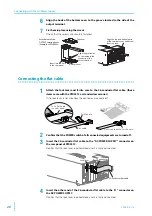
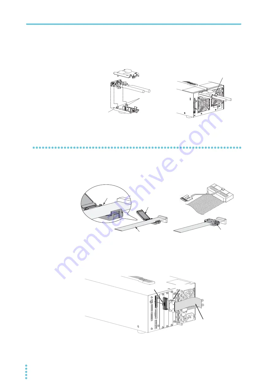
Align the hook of the bottom cover to the groove located to the side of the
output terminal.
7
Fix them in place using the screws.
Check that the screws are securely fastened.
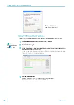
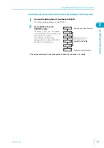
Connecting the flat cable
1
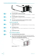
Attach the lock lever and ferrite core to the 26-conductor flat cable. (those
items come with the PFX2512 as standard accessories)
If the lock lever is not attached, the connector may come off.
2
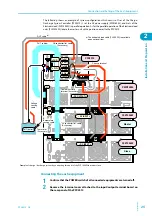
Confirm that the POWER switch of all connected equipments are turned off.
3
Insert the 26-conductor flat cable to the "DC POWER SUPPLY" connector on
the rear panel of PFX2512.
Confirm that the lock lever is pulled down and it is firmly connected.
4
Insert the other end of the 26-conductor flat cable to the "J1" connector on
the DC POWER SUPPLY.
Confirm that the lock lever is pulled down and it is firmly connected.
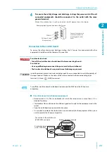
Top cover
Align the protrusion
on the inside to the
concavity of the
output terminal
Insert into the hole
in the rear panel
Bottom cover
Align the top and bottom parts
of the terminal cover and screw
them in place.
Attachment of the
OUTPUT terminal cover
(Example of PWR800L)
Flat cable
Ferrite core
Put a flat cable
in under hook.
Securrely lock the ferrite core.
26-conductor flat cable
Lock lever
Ferrite core
Summary of Contents for PFX2515
Page 10: ...10 PFX2512_CE This page is intentionally blank ...
Page 58: ...58 PFX2512_CE This page is intentionally blank ...
Page 59: ...Specification This chapter contains the PFX2512 specifications and outline drawings ...
Page 86: ...86 PFX2512_CE This page is intentionally blank ...
Page 100: ...100 PFX2512_CE This page is intentionally blank ...
Page 103: ......


