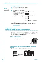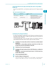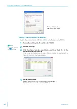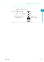
PFX2512_CE
31
Connecting with the Electronic Load
2
In
st
al
la
ti
on
a
n
d P
re
p
ar
a
ti
o
n
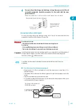
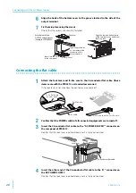
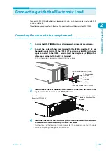
Connecting the flat cable
1
Attach the lock lever to the 20-concuctor
flat cable. (those items come with the
PFX2512 as standard accessories)
If the lock lever is not attached, the
connector may come off.
2
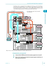
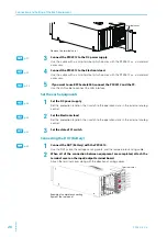
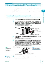
Confirm that the POWER switch of all connected equipments are turned off.
3
Insert the 20-conductor flat cable to the "DC ELECTRONIC LOAD" connector on
the rear panel of PFX2512.
Confirm that the lock lever is pulled down and it is firmly connected.
4
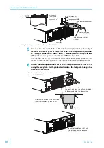
Insert the other end of the 20-conductor flat cable to the "J1" connector on
the PLZ-4W series.
Confirm that the lock lever is pulled down and it is firmly connected.
Ferrite core
20-conductor flat cable
Lock lever
Summary of Contents for PFX2515
Page 10: ...10 PFX2512_CE This page is intentionally blank ...
Page 58: ...58 PFX2512_CE This page is intentionally blank ...
Page 59: ...Specification This chapter contains the PFX2512 specifications and outline drawings ...
Page 86: ...86 PFX2512_CE This page is intentionally blank ...
Page 100: ...100 PFX2512_CE This page is intentionally blank ...
Page 103: ......


