38
PFX2512_CE
Setting the DC Power Supply
Set the protection function to protect the DUT (battery) and the connected equipments.
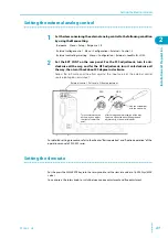
Set the external analog control to control the PFX2512.
PWR series
PAS series
It is recommended to set the lock function when all the settings are completed. It prevents from
being changed of setting by the operational error.
1
Set the PWR series, to the factory default settings. Turn on the POWER switch
while keep pushing the SHIFT key.
The contents of stored memory is cleared.
You cannot reset the PAS series to the factory default settings. Carry out the settings from step 2.
2
Set the protection functions.
If the factory setting were applicable, you don't need to set the protection functions.
3
Set the external analog control.
4
When the LOCK switch of the DC power supply is pressed, the LOCK switch
Illuminates and it locks the panel operation.
Press the LOCK switch again to release the panel lock.
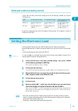
Setting the protection functions
If the unit of the DC power supply is set as the factory default settings, it is not necessary to set the
protection function.
Especially, when the DUT is concerned the safety as a matter of high priority or the charge and
discharge test is conducted with a risk, the level of safety can be improved by the setting of
protection functions.
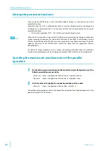
When the OVP or the OCP of the DC power supply activates while the charge and discharge testing
is executed, it becomes the state of the PS/B alarm by the PFX2512 and it turns off the output.
Please turn off the POWER switch of the DC power supply once, and remove the cause of the alarm.
After releasing the alarm of the DC power supply, turn on the POWER switch of the DC power
supply and release the alarm from the application software BPChecker3000.
For details of setting procedure such as setting and releasing the alarm when the protection
function is activated, please refer to the operation manual of the PWR series or PAS series, "Basic
operation".
Ope
• Even when the panel operation is locked, the key operation for the output on / off is enable to
function. Please note that if the output on/off operation is conducted during the charge and
discharge testing, it activates the alarm function and stop the testing.
• Adjustment is not required for connecting the equipments.
Model
Over voltage protection (OVP)
Over current protection (OCP)
PWR series
110 % of the maximum charge voltage
105 % of the maximum charge current
PAS series
110 % of the maximum charge voltage
110 % of the maximum charge current
See
Summary of Contents for PFX2515
Page 10: ...10 PFX2512_CE This page is intentionally blank ...
Page 58: ...58 PFX2512_CE This page is intentionally blank ...
Page 59: ...Specification This chapter contains the PFX2512 specifications and outline drawings ...
Page 86: ...86 PFX2512_CE This page is intentionally blank ...
Page 100: ...100 PFX2512_CE This page is intentionally blank ...
Page 103: ......


