48
PFX2512_CE
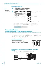
Connecting the DUT (battery)
Connecting the DUT cable
1
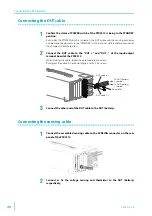
Confirm the status of POWER switch of the PFX2512 is being in the STANDBY
position.
Even when the POWER switch is turned on, the DUT cable and the sensing connector
can be disconnected only in the "STANDBY" state that must not be under execution of
the charge and discharge test.
2
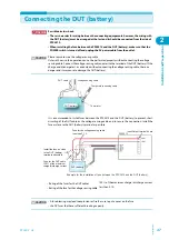
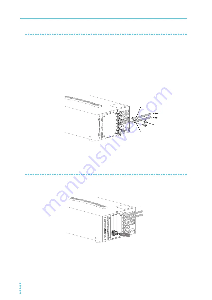
Connect the DUT cable to the "DUT +" and "DUT -" of the input/output
terminal board of the PFX2512.
When making the cable, follow the color code to be wired.
Pulling out the cable in horizontal angle and fix it by screws.
3
Connect the other end of the DUT cable to the DUT (battery).
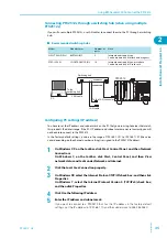
Connecting the sensing cable
1
Connect the assembled sensing cable to the SENSING connector on the rear
panel of the PFX2512.
2
Connect or fix the voltage sensing and thermistor to the DUT (battery)
respectively.
DUT cable (+)
DUT cable (–)
Screw (M6)
To DUT (battery)
– terminal
To DUT (battery)
+ terminal
Summary of Contents for PFX2515
Page 10: ...10 PFX2512_CE This page is intentionally blank ...
Page 58: ...58 PFX2512_CE This page is intentionally blank ...
Page 59: ...Specification This chapter contains the PFX2512 specifications and outline drawings ...
Page 86: ...86 PFX2512_CE This page is intentionally blank ...
Page 100: ...100 PFX2512_CE This page is intentionally blank ...
Page 103: ......

