
PLZ2004WB/PLZ2004WHB 1
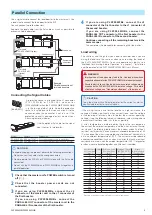
The PLZ2004WB/PLZ2004WHB Load Booster is used to increase the
input current to the PLZ1004W/PLZ1004WH Electronic Load. One
PLZ1004W/PLZ1004WH is made the master unit, and load boosters
connected in parallel operate as slave units.
Number of load
boosters
Maximum current/ Maximum power
PLZ2004WB
PLZ2004WHB
1
600 A / 3 000 W
150 A / 3 000 W
2
1
000 A / 5 000 W
250 A / 5 000 W
3
1
400 A / 7 000 W
350 A / 7 000 W
4
1
800 A / 9 000 W
450 A / 9 000 W
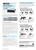
About the Operation Manual
This manual contains an overview of the PLZ2004WB/PLZ2004WHB
electronic load booster and information about connecting,
maintenance, and using it. For information on how to perform parallel
operation, see the PLZ-4W/PLZ-4WH Series Electronic Load User's
Manual.
These operation manuals are intended for users of electronic loads
and their instructors. Explanations are given under the presumption
that the reader has knowledge about Power Supply.
Every effort has been made to ensure the accuracy of this manual.
However, if you have any questions or find any errors or omissions,
please contact your Kikusui agent or distributor.
If you find any misplaced or missing pages in the manuals, they will
be replaced. If the manual gets lost or soiled, a new copy can be
provided for a fee. In either case, please contact your Kikusui agent
or distributor, and provide the "Kikusui Part No." given on the cover.
After you have finished reading this manual, store it so that you can
use it for reference at any time.
。
Features
•
Up to four load boosters can be connected in parallel.
•
The combination of PLZ2004WBs and a PLZ1004W master unit
can create an electronic load of up to 9 kW and 1 800 A.
The combination of PLZ2004WHBs and a PLZ1004WH master unit
can create an electronic load of up to 9 kW and 450 A.
The master unit displays the total current and total wattage. The
units connected in parallel can be used as a single electronic load.
•
The connection of the control cables is easy. The control cable
used to connect between the master unit and the load booster and
between each load booster is one flat cable each.
•
There is no power switch. The AC input power is turned ON/OFF
by the master unit.
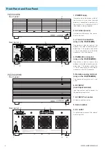
Checking the Package Contents
When you receive the product, check that all accessories are
included and that the product and accessories have not been
damaged during transportation. If any of the accessories are
damaged or missing, contact Kikusui distributor/agent.
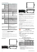
Accessories (PLZ2004WB)
Operation manual
(1 copy)
Load input terminal cover (2 pcs.)
[
with auxiliary band]
Set of screws for the load
input terminal (2 sets)
[M1-100-027]
[M5-101-009]
[M4-100-009]
[Q1-500-096]
[Q1-900-020]
Power cord
(1 pc.)
Heavy object warning label
(1 pc.)
If necessary, attach to the product.
Plug: NEMA5-15
Rating: 125Vac/10A
[85-AA-0003]
Plug: CEE7/7
Rating: 250Vac/10A
[85-AA-0005]
Plug: GB1002
Rating: 250Vac/10A
[85-10-0790]
or
or
The power cord that is provided varies depending on the
destination for the product at the factory-shipment.
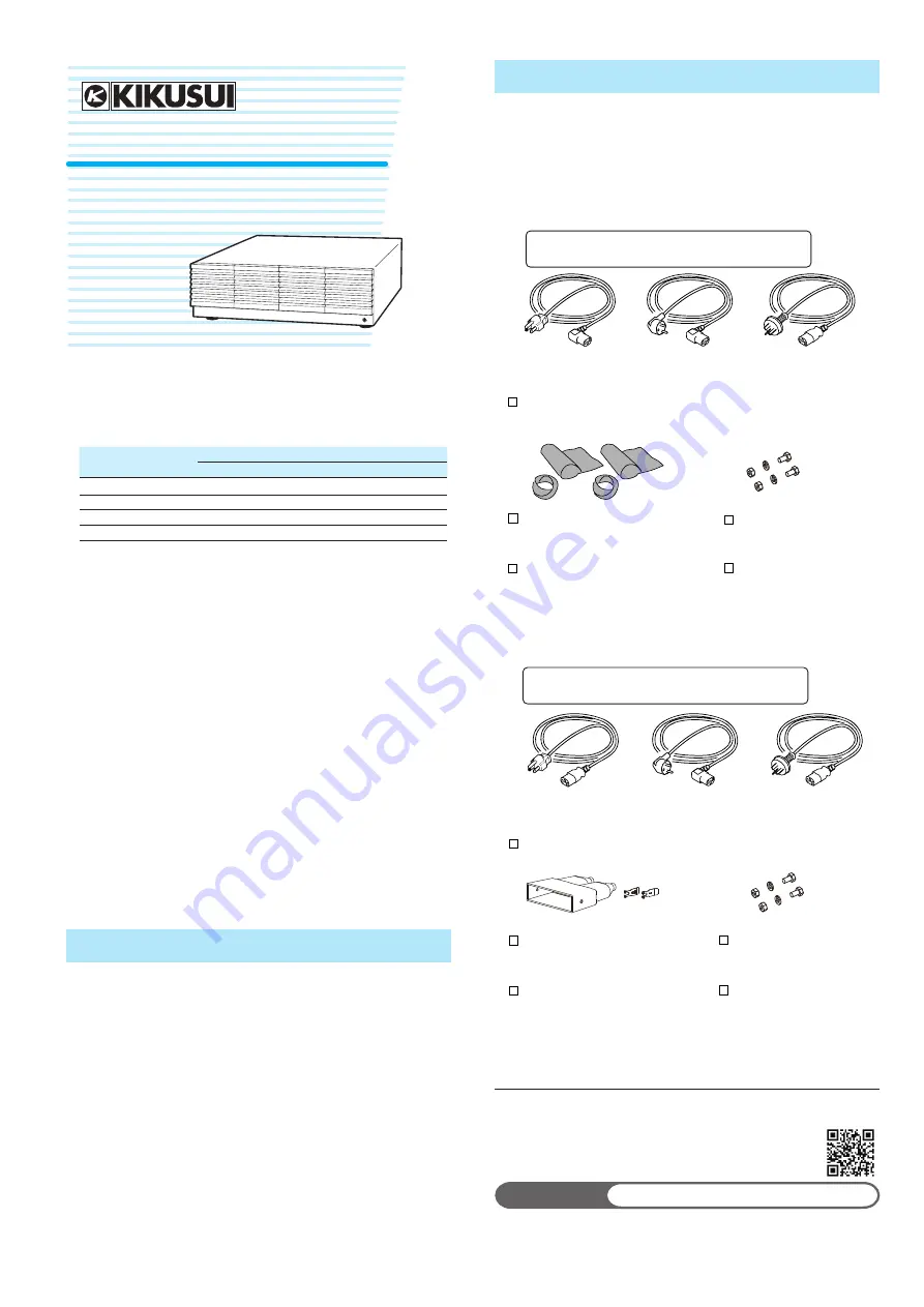
Accessories (PLZ2004WHB)
Load input terminal cover (1 pc.)
Lock plate (2 pcs.)
Set of screws for the load
input terminal (2 sets)
[M1-100-012]
[M5-101-007]
[M4-100-007]
[
Q1-500-085
]
[
P2-000-228
]
Power cord (1 pc.)
Plug: NEMA5-15
Rating: 125 Vac/10 A
[85-AA-0004]
Plug: CEE7/7
Rating: 250Vac/10A
[85-AA-0005]
Plug: GB1002
Rating: 250Vac/10A
[85-10-0790]
or
or
The power cord that is provided varies depending on the
destination for the product at the factory-shipment.
Operation manual
(1 copy)
Heavy object warning label
(1 pc.)
If necessary, attach to the product.
The newest version of the operation manual can be downloaded from
Download service of Kikusui website.
Website
http://www.kikusui.co.jp/en
KIKUSUI ELECTRONICS CORP.
1-1-3, Higashiyamata, Tsuzuki-ku, Yokohama,
224-0023, Japan
TEL: +81-45-593-0200 Fax: +81-45-593-7571
PART NO. Z1-005-160, IB022735
Oct. 2015
PLZ2004WB
PLZ2004WHB
Operation Manual
Electronic Load Booster


