Tutorial
KIKUSUI Electronics Corp.
PWR-01 Interface Manual
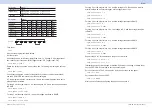
PWR-01 behavior during synchronized operation
Turn on the trigger input in a step of your choice on the PWR-01 operating in sync.
When all PWR-01s receive a hardware trigger (pin 7 of the TRIG IN terminal on the
rear panel) when the sequence is paused, the pause is released simultaneously on
all the PWR-01s. If the sequence information is written in the PWR-01, hardware
triggers can be used to release the pause state without a PC.
If PWR-01 are cascaded, turn on the trigger input and trigger output.
For details on the connection, see the user’s manual.
Status Monitoring
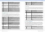
The PWR-01 has two mandatory SCPI standard registers, STATus:OPERation and
STATus:QUEStionable, in addition to the IEEE488.2 standard registers.
■
Register basics
All SCPI registers have standard event/filter architecture, employing CONDition,
EVENt, ENABle, and optionally PTRansition and NTRansition. CONDition and
EVENt are read-only registers working as status indicators, and ENABle, PTRansi-
tion and NTRansition are read-write registers working as event and summary filters.
■
STATus:OPERation
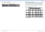
The STATus:OPERation register records events or signals that occur during normal
operation.
For example, to check if the PWR-01 is being regulated in CV state, check the CV
bit (bit 8) on the STATus:OPERation register.
STATus:OPERation?
'Check whether the CV bit is set
When multichannel is in use, check the CV bit (bit 8) of the STATus:OPERation:IN-
STrument:ISUMmary<n> subregister.
STATus:OPERation:INSTrument:ISUMmary2?
'Check whether the CV bit
of channel 2 is set.


