120
PWR-01
Specifications
|
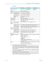
400W model
Output
PWR401L
PWR401ML
PWR401MH
PWR401H
Rating
Output voltage
1
40 V
80 V
240 V
650 V
Output current
40 A
20 A
5 A
1.85 A
Output power
400 W
Voltage
Maximum settable voltage
2
42 V
84 V
252 V
682.5 V
Setting accuracy
± (0.05 % of set +0.05 % of rating)
Resolution
200 mV
400 mV
1000 mV
2500 mV
Using FINE, OUT OFF
10 mV
10 mV
100 mV
100 mV
Using FINE, OUT ON
1 mV
1 mV
10 mV
10 mV
When using a communication
interface
1 mV
1 mV
10 mV
10 mV
Line regulation
3
±6 mV
±10 mV
±26 mV
±67 mV
Load regulation
4
±6 mV
±10 mV
±26 mV
±67 mV
Transient response
5
1 ms or less
2 ms or less
2 ms or less
3 ms or less
Ripple noise
6
p-p
7
50 mV
50 mV
100 mV
300 mV
rms
8
5 mV
5 mV
20 mV
50 mV
Rise time
At full load
50 ms or less
100 ms or less
No load
50 ms or less
100 ms or less
Fall time
9
At full load
50 ms or less
150 ms
250 ms
No load
500 ms or less
1200 ms
2000 ms
Maximum remote sensing compen-
sation voltage (single line)
1.5 V
4 V
5 V
5 V
Temperature coefficient
10
100 ppm/°C
Current
Maximum settable current
42 A
21 A
5.25 A
1.9425 A
Setting accuracy
11
± (0.5 % of set +0.1 % of rating)
Resolution
200 mA
100 mA
20 mA
10 mA
Using FINE, OUT OFF
10 mA
10 mA
1 mA
1 mA
Using FINE, OUT ON
1 mA
1 mA
0.1 mA
0.1 mA
When using a communication
interface
1 mA
1 mA
0.1 mA
0.1 mA
Line regulation
±6 mA
±4 mA
±2.5 mA
±2.2 mA
Load regulation
±13 mA
±9 mA
±6.0 mA
±5.4 mA
Ripple noise
12
rms
80 mA
40 mA
12 mA
6 mA
Rise time (TYP)
At full load
50 ms
100 ms
Fall time (TYP)
At full load
50 ms
100 ms
Temperature coefficient
100 ppm/°C
Maximum internal resistance that can be set
1.000
Ω
4.000
Ω
36.00
Ω
263.5
Ω
1.
The maximum output voltage and maximum output current are limited by the maximum output power.
2.
Can be limited to approximately 95 % of the OVP trip point or OCP trip point.
3.
85 Vac to 135 Vac or 170 Vac to 265 Vac, fixed load
4.
The amount of change that occurs when the load is changed from no load to full load (rated output power/
rated output voltage) with rated output voltage. The value is measured at the sensing point.
5.
The amount of time required for the output voltage to return to a value within "rated output voltage ± (0.1 % +
10 mV)." The load current fluctuation is 50 % to 100 % of the maximum current with the set output voltage.
6.
Measured using an RC-9131C probe that conforms to the JEITA specifications. At the rated output current.
7.
When the measurement frequency bandwidth is 10 Hz to 20 MHz.
8.
When the measurement frequency bandwidth is 10 Hz to 1 MHz.
9.
When the bleeder circuit is set to bleeder normal.
10.
When the ambient temperature is within 0°C and 50 °C
11.
Applies to the range of 1 % to 100 % of the rated current. TYP (
0.1 % of rating) for 0 % to 1 %.
12.
When the output voltage is 10 % to 100 % of the rating. At the rated output current.
Summary of Contents for PWR1201H
Page 7: ...PWR 01 7 This page is intentionally blank ...
Page 12: ...12 PWR 01 This page is intentionally blank ...
Page 74: ...74 PWR 01 This page is intentionally blank ...
Page 100: ...100 PWR 01 This page is intentionally blank ...
Page 112: ...112 PWR 01 This page is intentionally blank ...
Page 113: ...Maintenance This chapter explains how to perform cali bration ...
Page 134: ...134 PWR 01 This page is intentionally blank ...
Page 135: ...Appendix A Factory Default Settings B Options C Troubleshooting ...
Page 144: ...144 PWR 01 ...


