background image

66

PWR-01

Basic Features

CONFIG Settings

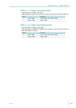
CF60 (

BOOT

)  LAN setting reset (LCI/ dEF)/ apply (APPL)

Sets whether to reset or apply the LAN interface settings (

p.57

).

Then, press SET twice to execute the reset or application.
If you select to reset the LAN interface settings (

LCI 

(LCI)/ 

DEF 

(Default)), the security

password will be cleared, and the PWR-01 will be in a security-disabled state.
If the LAN LED turns red (

p.9

), set the settings again.

For details on the LAN interface settings, see the “Communication Interface Manual” on the
included CD-ROM.

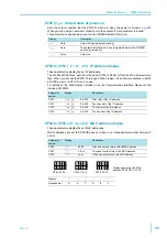
CF61 (

ADR

)  IP address assignment method

Sets the IP address assignment method.
Set whether to use (on: 1) or not use (off: 0) the following: DHCP server, AUTO IP function
(automatic assignment), and MANUAL IP function (manual assignment).
If DHCP and AUTO IP are both set to on and an IP address is not assigned through a DHCP
server, AUTO IP is used.
To use MANUAL IP, set DHCP and AUTO IP to off. The IP address that is assigned by the
AUTO IP function is 169.254.x.x (where x is a number between 1 and 254).
This parameter is applied when you turn the POWER switch off and on or when you execute

APPL 

(Apply) with CF60.

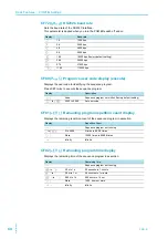
CF62 to CF65 (

S.IP1

 to 

S.IP3

)  Manual IP address setting (MANUAL IP)

If you are not using the DHCP server or the AUTO IP function, set the IP address manually.
To do so, use CF61 to set MANUAL IP to on.
This parameter is applied when you turn the POWER switch off and on or when you execute

APPL 

(Apply) with CF60.

Display

Description

LCI

LAN Configuration Ini-
tialize

Resets the LAN interface settings (to their factory default 
values)

DEF

Default

The LAN interface and multichannel (VMCB) settings are 
reset (to their factory default values).

APPL

Apply

The LAN interface is restarted, and the CONFIG settings are
applied.

Display

Description

001

001

DHCP: off, AUTO IP: off, MANUAL IP: on

010

010

DHCP: off, AUTO IP: on, MANUAL IP: off

011

011

DHCP: off, AUTO IP: on, MANUAL IP: on

100

100

DHCP: on, AUTO IP: off, MANUAL IP: off

101

101

DHCP: on, AUTO IP: off, MANUAL IP: on

110

110

DHCP: on, AUTO IP: on, MANUAL IP: off (factory default setting)

111

111

DHCP: on, AUTO IP: on, MANUAL IP: on

Parameter 
number

Display

Description

CF62

0.

 to 

255

0 to 255

 First octet of the IP address

CF63

0.

 to 

255

0 to 255

 Second octet of the IP address

CF64

0.

 to 

255

0 to 255

 Third octet of the IP address

CF65

0.

 to 

255

0 to 255

 Fourth octet of the IP address

Summary of Contents for PWR1201H

Page 1: ...Supply 45 Protection functions and Alarms 46 CONFIG Settings 54 Preset Memory function 70 Locking Panel Controls Key Lock 71 CONFIG Shortcut function 72 Switching from Remote Mode to Local Mode 73 Advanced Features 75 Bleeder Circuit function 76 Variable Internal Resistance function 78 Sequence function 79 Synchronized Operation 80 External Control 83 Product Operation 84 About the J1 J2 Connector...

Page 2: ...el Firmware version see page 28 Serial number displayed on the top panel Trademarks Microsoft Internet Explorer and Windows are registered trademarks or trademarks of Microsoft Corporation in the United States and or other countries All company names and product names used in this manual are trademarks or registered trademarks of their respective companies Copyrights The contents of this document ...

Page 3: ...You can apply limits to the voltage and current settings This prevent you from setting an appropriate value by mistake which would cause the output to turn off Overcurrent protection OCP detection time setting You can set the amount of time that an overcurrent must persist after the first detection of the overcurrent before the overcurrent protection OCP is activated If inrush current from the loa...

Page 4: ...e illustrations of displays used in this manual may differ from the actual displays The illustrations are merely exam ples The following markings are used in the explanations of this text Indicates a potentially hazardous situation which if ignored could result in death or serious injury Indicates a potentially hazardous situation which if ignored may result in damage to the product or other prope...

Page 5: ...pply 45 Protection functions and Alarms 46 Alarm occurrence and clearing alarms 46 Setting the protection functions 47 Setting limits 52 CONFIG Settings 54 CONFIG parameter details 58 Preset Memory function 70 Saving settings 70 Recalling settings 70 Locking Panel Controls Key Lock 71 CONFIG Shortcut function 72 Registering CONFIG shortcuts 72 Using CONFIG shortcuts 72 Switching from Remote Mode t...

Page 6: ...aintenance Calibration 114 Calibration overview 114 Calibration procedure 115 Cleaning 116 7 Specifications 400W model 119 800W model 122 1200W model 125 Common specifications 128 Appe ndix A Factory Default Settings 136 B Options 138 C Troubleshooting 140 ...

Page 7: ...PWR 01 7 This page is intentionally blank ...

Page 8: ...SPL MEMORY LOCAL SET OVP OCP CV CC W V A ALM RMT LOCK LAN B C A PRESET DLY SEQ HB SS VIR CV CC W V A ALM RMT LOCK LAN SC2 SC3 LOCK ALM CLR SC1 SHIFT FINE FINE REGULATED DC POWER SUPPLY OUTPUT VOLTAGE CURRENT CONFIG PWR DSPL MEMORY LOCAL SET OVP OCP CV CC W V A ALM RMT LOCK LAN B C A PRESET DLY SEQ HB SS VIR CV CC W V A ALM RMT LOCK LAN SC2 SC3 LOCK ALM CLR SC1 SHIFT FINE FINE REGULATED DC POWER SU...

Page 9: ...IG key Used to configure the various operating conditions CONFIG the key has an LED p 54 SC2 Used to call the CONFIG parameter shortcut the key has an LED p 72 11 VOLTAGE knob Used to set the voltage value or select the value of a CONFIG parameter p 36 p 54 FINE Used to make fine voltage value adjustments p 36 12 CV LED Lights green during constant voltage mode p 45 13 CC LED Lights red during con...

Page 10: ...10 PWR 01 Rear Panel J1 J2 J2 J1 J2 J1 9 8 10 11 8 8 9 9 400W model 800W model 1200W model 7 4 5 6 1 3 2 10 11 10 11 ...

Page 11: ...ssis 5 TRG OUT connector1 Trigger signal output terminal The common terminal is connected to the chassis 6 USB port1 1 A connector cover or terminal cover is attached when the product is shipped from the factory USB port for controlling the PWR 01 remotely 7 Sensing terminal Terminals to connect the sensing cables to p 30 8 Air outlet Air outlet for internal cooling 9 AC INPUT 400W model 800W mode...

Page 12: ...12 PWR 01 This page is intentionally blank ...

Page 13: ...Installation and Preparation This chapter describes how to turn on the PWR 01 what kind of load cables to use and how to connect cables to the output terminals ...

Page 14: ...has a protective con ductor terminal Be sure to earth ground the product to prevent electric shock The product is grounded through the power cord ground wire Connect the protec tive conductor terminal to earth ground Use the included power cord to connect to the AC line If the supplied power cord cannot be used because the rated voltage or the plug shape is incompatible have a qualified engineer s...

Page 15: ... the switchboard breaker a switch that cuts off the power supply from the switchboard Risk of fire Be sure to have a qualified engineer make the connection to the switchboard The switchboard breaker must meet the requirements shown below CAUTION Inside the product protection circuits are connected to match the polarity of the input termi nal Be sure to connect the L N and GND terminals correctly b...

Page 16: ...the AC INPUT terminal on the rear panel Pass the power cord through the included INPUT terminal cover and fix the cord in place using the lock plate and screws Be sure to connect the L N and GND of the AC input terminal correctly 4 Attach the INPUT terminal cover using the screws on the PWR 01 5 Attach the included ferrite core to the power cord 400W model 800W model 1200W model Protective conduct...

Page 17: ...on to the power cord Check that the core is locked and does not move Cut the cable tie at an appropriate length 6 Attach a appropriate crimping terminal to the switchboard end of the power cord 7 Turn off the switchboard s circuit breaker 8 Connect the L N and GND wires of the power cord to the matching terminals on the switchboard Insert the cable tie through here Firmly apply the cable tie to at...

Page 18: ...Therefore if a regenerative load such as an inverter converter or transformer is connected the output voltage increases and becomes unstable This can cause a malfunction For these types of loads connect a resistor RD as shown in the following figure to bypass the reverse current However the amount of current to the load decreases by Irp Load current with peaks Pulse shaped load current Constant cu...

Page 19: ... 01 and the load in series as shown in the following figure This cannot be used in conjunction with remote sensing This product Load with accumulated energy DRP Reverse current protection diode DRP CAUTION To protect the load and the PWR 01 use a DRP that conforms to the following specifications Reverse voltage withstand capacity At least twice the rated output voltage of the PWR 01 Forward curren...

Page 20: ...e against unwanted noise The Kikusui recommended currents shown in the above table are allowable currents that have been reduced in consideration of the potential bundling of load cables Use these values as a guideline when connecting cables WARNING Risk of fire Use load cables whose capacity is adequate for the PWR 01 s rated output current The output terminal and its surrounding area become very...

Page 21: ...the wire becomes greater This results in a smaller voltage being applied at the load end The PWR 01 has a sensing function that compensates for this voltage drop up to the following values p 30 If the voltage drop exceeds this level use cables that have a greater cross sectional area L type ML type MH type H type Compensation voltage Approx 1 5 V one way Approx 4 V one way Approx 5 V one way Appro...

Page 22: ... an insulation capacity greater than or equal to the isolation voltage of the PWR 01 WARNING Risk of electric shock For safety reasons even if the output terminal is grounded make sure that the insulation capacity of the output terminal including the sensing terminal is greater than or equal to the isolation voltage of this product For details on the isolation voltage of each model see Specificati...

Page 23: ... true when the negative terminal is connected to the chassis terminal The cable and load require an insulation capacity that is greater than or equal to the maximum output voltage of the PWR 01 For safety reasons connect one of the output terminals to the chassis terminal unless your application requires the output terminals to be floating S S 16 17 18 19 14 15 20 2 3 4 5 6 13 12 11 10 9 8 7 1 2 3...

Page 24: ...ad cables The rear panel output terminals have holes for connecting the load cables Use crimp ing terminals that are appropriate for the bolts that you are using WARNING Risk of electric shock Turn the POWER switch off before you touch the rear panel output terminals Even if you turn the output off or turn the POWER switch off if the bleeder circuit is set to off CF01 DIS the voltage that was pres...

Page 25: ...g the insulation up to ø7 Attach the adapter of the OUTPUT terminal cover so that the hole diameter is small Cable diameter including the insulation from ø8 to ø17 Attach the adapter of the OUTPUT terminal cover so that the hole diameter is large Memo If you do not connect load cables in the correct orientation you will not be able to attach the OUTPUT terminal cover Spring washer M8 Washer M8 Was...

Page 26: ...d bottom halves of the OUTPUT terminal cover have different shapes Top half of the cover For thin load cables Cable diameter including the insulation ø8 to ø17 Cable diameter including the insulation Up to ø7 For thick load cables Top half of the cover Example of the load cable position Example of the load cable position Insert the adapter tabs into the two cuts in the top half Insert the adapter ...

Page 27: ...essary cables and plugs recommended Polyvinyl chloride insulation cable Nominal cross sectional area of 0 33 mm2 AWG22 to 0 82 mm2 AWG18 Rated voltage 1000 V or higher Length Less than 3 m Output terminal plugs Safety plugs Safety plugs TL41 and TL42 are available as options p 139 1 Attach safety plugs to the load cables 2 Connect the load cables with safety plugs to the front panel output ter min...

Page 28: ...e voltmeter and the ammeter display the following sequence of information the rated voltage and rated current the firmware version number and then the build number Each item is displayed for approximately 1 sec ond After a few seconds the PWR 01 enters the operation standby state the measured value is displayed WARNING Risk of electric shock Regardless of whether load cables are connected to the o...

Page 29: ...the PWR 01 when the POWER switch is turned on p 65 If the POWER switch is turned off immediately after the settings have been changed the last settings may not be stored CAUTION After you turn the POWER switch off wait at least 10 seconds after the panel display turns off before you turn the POWER switch back on Repeatedly turning the POWER switch on and off at short intervals can cause damage to ...

Page 30: ...en the product is shipped from the factory a sensing short bar is connected across the sensing terminals and DC OUTPUT termi nals When the sensing terminals are not used connect the sens ing short bar If the short bar is damaged or lost contact your Kikusui agent or distributor Connecting the sensing cables L type ML type MH type H type Compensation voltage Approx 1 5 V one way Approx 4 V one way ...

Page 31: ...r that is connected across the sensing ter minals and DC OUTPUT terminals 3 Attach crimping terminals to the sensing cables and connect the sens ing terminals to the sensing point across the load Attach crimping terminals that match the screws to be used and securely fasten the cables If you cannot use shielded cables twist the positive and negative cables sufficiently Capacitor S S Connect an ele...

Page 32: ...lizes the voltage However if this does not correct the problem connect an electrolytic capacitor across the load Electrolytic capacitor to use Capacitance 0 1 µF to several 100 µF Withstanding voltage At least 120 of the rated output voltage of the PWR 01 If you are inserting a mechanical switch between the PWR 01 and the load If you want to connect and disconnect the load using a mechanical switc...

Page 33: ...Basic Features This chapter describes how to turn the out put on and off and the basic operations that you can perform from the front panel ...

Page 34: ... light the key and display the present overcurrent protection and overvoltage protection settings Press OVP OCP again the present undervoltage limit value is displayed CV CC W V A ALM RMT LOCK LAN B C A PRESET DLY SEQ HB SS VIR CV CC W V A ALM RMT LOCK LAN SC2 SC3 LOCK ALM CLR SC1 SHIFT FINE FINE REGULATED DC POWER SUPPLY OUTPUT VOLTAGE CURRENT CONFIG PWR DSPL MEMORY LOCAL SET OVP OCP CV CC W V A ...

Page 35: ...Press CONFIG to light the key and display the current system configuration settings CV CC W V A ALM RMT LOCK LAN B C A PRESET DLY SEQ HB SS VIR CV CC W V A ALM RMT LOCK LAN SC2 SC3 LOCK ALM CLR SC1 SHIFT FINE FINE REGULATED DC POWER SUPPLY OUTPUT VOLTAGE CURRENT CONFIG PWR DSPL MEMORY LOCAL SET OVP OCP Lit ...

Page 36: ...When the output is on amount of change becomes even smaller The displayed current or voltage may not change even if you turn the VOLTAGE or CUR RENT knob This is because the value is being changed at a higher resolution than what is shown In this situation the display will change when the amount that you change the value by reaches the smallest display digit of the set voltage or current CV CC W V...

Page 37: ...by mistakenly setting the voltage or current to a value that exceeds the set OVP or OCP trip point or avoid setting a value that is lower than the set UVL trip point Output on off setting at power on By factory default the output is off when the power is turned on Using a CONFIG setting you can set the output state at power on p 65 Output on startup state parameter You can set whether to start the...

Page 38: ... delay is in effect DLY and the OUTPUT LED blink orange if set to on green if set to off If you press OUTPUT when the output on off delay is in effect the process is canceled and the output is turned off If you press OUTPUT again the output on delay resumes Off Off Blinking Lit Blinking Lit Lit Blinking Lit Blinking Delay Delay Delay Off Lit Blinking On orange orange orange green green green green...

Page 39: ...s green When soft stop is in effect SS and the OUTPUT LED blink green If you press OUTPUT when soft start or soft stop is in effect the process is canceled and the output is turned off If you press OUTPUT again soft start resumes If the bleeder circuit is set to off the output current may not fall gradually even if soft stop is used 0 1s 0 1s 0 1s Actually each transition takes place over 0 1 s Bl...

Page 40: ...s used Waveform when soft stop is used 5 0 0 0 5 5 0 10 0 Time s Voltage V Ÿ UHSUHVHQWV WKDW WKH 287387 NH KDV EHHQ SUHVVHG 2XWSXW off 2XWSXW RQ Outpu on Output voltage 5 V Soft start time 5 0 s CF06 5 0 5 0 0 0 5 5 0 10 0 Time s Voltage V Output on Output off Ÿ UHSUHVHQWV WKDW WKH 287387 NH KDV EHHQ SUHVVHG Outpt off Output voltage 5 V Soft stop time 5 0 s CF07 5 0 s ...

Page 41: ... 105 of the rated output power and the output voltage and output current change depending on the load value Output current A Output voltage V 35 30 45 40 25 20 15 10 5 0 0 5 10 15 20 25 30 45 0 10 20 30 40 50 60 35 70 40 80 90 0 15 30 45 60 75 90 105 120 135 Rated output current Rated output power Rated output power L type Operating range Rated output voltage 40 V PWR401L PWR801L PWR1201L PWR401L ...

Page 42: ...utput voltage 240 V PWR401MH PWR801MH PWR1201MH MH type Operating range PWR401MH 400 W PWR801MH 800 W PWR1201MH 1200 W Output voltage V 700 600 500 100 200 400 300 0 0 0 2 0 4 1 1 2 1 6 0 0 4 0 8 0 6 1 2 2 0 8 1 6 2 4 1 4 2 8 3 2 1 8 3 6 2 4 Output current A 0 0 6 1 2 1 8 3 2 4 3 6 4 2 4 8 5 4 6 Rated output current Rated output power Rated output power Rated output voltage 650 V PWR401H PWR801H P...

Page 43: ...ent that is less than current limit Is The actual current that flows is not necessarily equal to the specified value For loads in which transient peak current flows current limit Is must be set higher than the peak value Conversely if load resistance RL is less than resistance Rc the operating point is in area and the PWR 01 operates in CC mode point q In this case set voltage Vs equals the volt a...

Page 44: ...A 8 Ω 40 V If you try to increase the voltage above this point the crossover point is reached and the power supply automatically switches to CC mode To maintain oper ations in CV mode increase the current limit Next a load resistance RL of 5 Ω is connected to the output terminals of the power supply The output voltage and output current are set to 30 V and 5 A respectively In this case Rc 30 V 5 A...

Page 45: ...n set the voltage and current by carrying out Step2 and Step3 while checking the actual output voltage or current You can set the voltage that is actually output while checking the power p 34 You can use the CONFIG settings to set the output on startup state CF02 CV CC p 58 Set this according to the operation mode that you are using You can prevent overshoot from occurring when the output is turne...

Page 46: ... indication of the cause of alarm OUTPUT LED blinking orange if the protection function was activated when the output was on When a CONFIG parameter is being displayed the cause of alarm is not displayed Alarm signal output Alarm signal generated from pin 14 of the J1 connector if PRL ALM or SD is activated Alarm signal generated from pin 4 of the J2 connector if OVP OCP FOCP OHP SENSE AC FAIL WAT...

Page 47: ...oltage setting Setting the OVP trip point OVP operates on the output terminal voltage If you want to activate the protection function according to the voltage across the load take the voltage drop in the load cable into consider ation when you set the OVP trip point 1 Press OVP OCP The OVP OCP key lights and the voltmeter displays the present OVP trip point 2 Turn the VOLTAGE knob to set the OVP t...

Page 48: ...t current OCP trip point You need to set an appropriate OCP trip point Immediately after you purchase the PWR 01 or immediately after a load is changed set the OCP trip point to a value that is appropriate for the load If the current setting limit is set to on CF22 ON you cannot set an OCP trip point that is lower than the current setting You can set the detection time of OCP activation Setting th...

Page 49: ...t the OUTPUT LED is turned off 4 Set the output current to a value lower than the OCP trip point 5 Press OUTPUT to turn output on The OUTPUT LED lights 6 Slowly turn the CURRENT knob clockwise until the OCP is activated When the output current exceeds the OCP trip point an alarm will occur The ALM LED lights and the OUTPUT LED blinks 7 Check that output has turned off 8 Press ALM CLR SHIFT SET to ...

Page 50: ... is detected You can set the PWR 01 so that when the problem that caused the AC FAIL to be activated is corrected the output is automatically turned on CF20 AUTO Activation and release are repeated according to the variation in the AC power line CV CC W V A ALM RMT LOCK LAN B C A PRESET DLY SEQ HB SS VIR CV CC W V A ALM RMT LOCK LAN SC2 SC3 LOCK ALM CLR SC1 SHIFT FINE FINE REGULATED DC POWER SUPPL...

Page 51: ...nit detects the alarm and shuts down the output of the entire system This function protects devices by preventing the master unit and the remaining slave units from continuing the output Connect pin 14 of the J1 connectors of the master unit and slave units To release PRL ALM turn the POWER switch off and then back on Alarm indication based on communication monitoring watchdog CV CC W V A ALM RMT ...

Page 52: ...ing limit CF23 By factory default the voltage setting limit is set to on CF23 ON If you enable the voltage setting limit when the voltage setting is less than the set UVL trip point the voltage setting is retained but the UVL trip point is changed to the voltage setting Setting the UVL trip point 1 Press OVP OCP twice The present UVL trip point is displayed 2 Turn the VOLTAGE knob to set the UVL t...

Page 53: ... when the current setting is higher than 95 of the OCP trip point the current setting is retained but the OCP trip point is changed to 105 of the current setting Power limit POWER LIMIT This function limits the output power to a value that is approximately 105 of the rated out put power This function changes the output voltage or output current according to the changes in the load resistance p 41 ...

Page 54: ... voltage external resistance CF12 E RNG Control range CV CC control range CF131 M RNG Monitor range Voltage Current monitor output range CF14 E OUT Ext on off External control for turning output on off CF15 E LOG Ext logic External control logic for turning output on off CF16 STS C Stat CC pol CC status signal polarity CF17 STS V Stat CV pol CV status signal polarity CF18 STS O Stat Output pol Out...

Page 55: ...bnet Mask IP address subnet mask CF67 DOM VMCB Dom Multichannel VMCB domain number 2 CF68 CH VMCB Ch Multichannel VMCB channel number 2 USB CF70 VID V ID Vendor ID VID display CF71 PID P ID Product ID PID display RS232C CF72 BAUD Baud rate RS232C baud rate Sequence CF80 PROG Program Program s user code display execute CF81 REM L Rem Loop Remaining program repetition count display CF82 REM T Rem Ti...

Page 56: ... BLE OFF D VOLTAGE knob LOCAL key E CC E CV STS A VOLTAGE knob LOCAL key A RCU WDOG OC DL VOLTAGE knob LOCAL key SC1 SC2 AMTR VOLTAGE knob LOCAL key LAN USB PON VOLTAGE knob LOCAL key IP1 IP2 HA3 VOLTAGE knob LOCAL key BOOT ADR CH VOLTAGE knob LOCAL key VID PID BAUD VOLTAGE knob LOCAL key PROG REM L TRG O VOLTAGE knob LOCAL key VOLTAGE knob VOLTAGE knob VOLTAGE knob VOLTAGE knob LAN settings displ...

Page 57: ...ue display appears or press PWR DSPL There are parameters whose values are applied immediately those whose values are applied after the power is turned off and then back on and those whose values are applied when APPL is executed using CF60 p 54 CONFIG setting and display examples CV CC W V A ALM RMT LOCK LAN B C A PRESET DLY SEQ HB SS VIR CV CC W V A ALM RMT LOCK LAN SC2 SC3 LOCK ALM CLR SC1 SHIF...

Page 58: ... startup state Sets the prioritized operation mode when the output is turned on p 45 When used as a slave device CC is automatically prioritized Output on off Soft start stop time CF04 to CF07 Output voltage Output on off delay CF08 CF09 Output current Constant current control using an external voltage external resistance CF10 Overvoltage protection Constant voltage control using an external volta...

Page 59: ...ally CF08 ON D Output on delay setting You can set the delay from when the OUTPUT key is pressed to when the output actually turns on p 38 Display Description OFF OFF Variable internal resistance function is not used factory default setting Rint min to Rint max Rint min Ω to Rint max Ω Display Description 0 0 0 0 Disable soft start factory default setting 0 5 to 10 0 0 5 to 10 0 Soft start time 0 ...

Page 60: ...1 3 REFOUT is also set to 5 25 V CF12 LO or 10 5 V CF12 HI according to the range setting CF13 M RNG Voltage Current monitor output range Sets the voltage range when monitoring voltage or current p 98 You can also set this parameter when the PWR 01 is being used as a slave unit CF14 E OUT External control for turning output on off Enables or disables output on off control using an external contact...

Page 61: ...t protection AC FAIL is released p 46 This parameter is applied when you turn the POWER switch off and on You can also set this parameter when the PWR 01 is being used as a slave unit Display Description LO LOW The output is turned on with a low signal 0 V to 0 5 V or short cir cuit factory default setting HI HIGH The output is turned on with a high signal 4 5 V to 5 V or open cir cuit Display Des...

Page 62: ...this parameter when the PWR 01 is being used as a slave unit CF30 SC1 CONFIG parameter shortcut registration SC1 Registers a CONFIG setting parameter to the front panel s SC1 key p 72 CF31 SC2 CONFIG parameter shortcut registration SC2 Registers a CONFIG setting parameter to the front panel s SC2 key p 72 Display Description OFF OFF Communication monitor timer is set to off factory default setting...

Page 63: ... Slave unit display during master slave parallel oper ation Sets whether the current or power on slave units is displayed during master slave parallel operation If the slave unit display is disabled the ammeter shows CF40 LAN LAN interface setting Enables or disables the LAN interface By setting this parameter to OFF you can disable the LAN interface function even when a LAN cable is connected Thi...

Page 64: ...o use the PWR 01 as a master unit or slave unit in master slave parallel oper ation p 102 If you want to use the PWR 01 as a master unit set the total number of units If you want to use the PWR 01 as a slave unit select SLAV Slave This parameter is applied when you turn the POWER switch off and on You can also set this parameter when the PWR 01 is being used as a slave unit Display Description OFF...

Page 65: ...ameters display the set MAC addresses MAC addresses are set to 00 0F CE xx xx xx where x is a hexadecimal number between 0 and F Display Description SAFE Safe Output off factory default setting AUTO Auto The output state that was in use immediately before the POWER switch was turned off FORC Force Output on Parameter number Display Description CF50 0 to 255 0 to 255 First octet of the IP address C...

Page 66: ...e POWER switch off and on or when you execute APPL Apply with CF60 CF62 to CF65 S IP1 to S IP3 Manual IP address setting MANUAL IP If you are not using the DHCP server or the AUTO IP function set the IP address manually To do so use CF61 to set MANUAL IP to on This parameter is applied when you turn the POWER switch off and on or when you execute APPL Apply with CF60 Display Description LCI LAN Co...

Page 67: ...M CF68 CH Multichannel VMCB channel number Set the multichannel channel number Specify a unique number on the network If you do not want to use the multichannel function set this to 0 this is the factory default setting This parameter is applied when you turn the POWER switch off and on For details on the multichannel function see the Communication Interface Manual on the included CD ROM CF70 VID ...

Page 68: ...equence program in execution Display Baud rate 1 2 1 2 1200 bps 2 4 2 4 2400 bps 4 8 4 8 4800 bps 9 6 9 6 9600 bps 19 2 19 2 19200 bps factory default setting 38 4 38 4 38400 bps 57 6 57 6 57600 bps 115 2 115 2 115200 bps Display Description NONE None Sequence program not written factory default setting 0000 to 9999 0000 to 9999 Set user code Display Repetition Count Sequence program not running 0...

Page 69: ...igger output signal polarity Sets the polarity of the trigger output signal Trigger signals are output when a program step is resumed or when the output is turned on must be set with a command Display Description PTR Positive Trigger Positive trigger factory default setting NTR Negative Trigger Negative trigger Display Description PTR Positive Trigger Positive trigger factory default setting NTR N...

Page 70: ...RESET LED lights and the settings are saved Recalling settings You can recall settings from the preset memory on the measured value display when the SET key is off or the setting display when the SET key is lit If the output is on the settings are applied to the output the moment they are recalled 1 Press MEMORY to select the preset memory entry PRESET A B or C you want to recall the settings from...

Page 71: ...put voltage and output cur rent as necessary 2 Hold down LOCK SHIFT PWR DSPL until the LOCK LED turns on The LOCK LED lights and the keys are locked To unlock the keys hold down LOCK again SHIFT PWR DSPL until the LOCK LED turns off CV CC W V A ALM RMT LOCK LAN B C A PRESET DLY SEQ HB SS VIR CV CC W V A ALM RMT LOCK LAN SC2 SC3 LOCK ALM CLR SC1 SHIFT FINE FINE REGULATED DC POWER SUPPLY OUTPUT VOLT...

Page 72: ...sing CONFIG shortcuts 1 Press SHIFT SC1 SC2 or SC3 in which the CONFIG parameter you want to recall is registered The registered CONFIG parameter is displayed 2 Hold down CONFIG until the measured value display appears or press PWR DSPL CV CC W V A ALM RMT LOCK LAN B C A PRESET DLY SEQ HB SS VIR CV CC W V A ALM RMT LOCK LAN SC2 SC3 LOCK ALM CLR SC1 SHIFT FINE FINE REGULATED DC POWER SUPPLY OUTPUT ...

Page 73: ...he display area lights To switch the PWR 01 to local mode from the front panel press LOCAL CV CC W V A ALM RMT LOCK LAN B C A PRESET DLY SEQ HB SS VIR CV CC W V A ALM RMT LOCK LAN SC2 SC3 LOCK ALM CLR SC1 SHIFT FINE FINE REGULATED DC POWER SUPPLY OUTPUT VOLTAGE CURRENT CONFIG PWR DSPL MEMORY LOCAL SET OVP OCP Lit ...

Page 74: ...74 PWR 01 This page is intentionally blank ...

Page 75: ...Advanced Features This chapter describes how to use advanced operations such as the bleeder circuit function variable internal resistance function sequence function and synchro nized operation ...

Page 76: ...tput terminals even if you turn off the out put or POWER switch Bleeder circuit Displayed setting Description Off1 1 Even if the output terminals are open and the output is turned off or the voltage setting is at 0 V up to several hundred millivolts of voltage may appear across the output terminals DIS Bleeder circuit off Normal bleeder NORM Bleeder circuit on Hyper bleeder HYP Bleeder circuit on ...

Page 77: ...34 A 0 114 A 0 072 A 0 056 A Hyper bleeder 0 223 A 0 221 A 0 208 A 0 187 A 0 145 A 0 128 A PWR801MH Off 0 000 A 0 000 A 0 000 A 0 001 A 0 001 A 0 002 A Normal bleeder 0 304 A 0 295 A 0 267 A 0 221 A 0 128 A 0 091 A Hyper bleeder 0 441 A 0 432 A 0 407 A 0 364 A 0 279 A 0 250 A PWR1201MH Off 0 000 A 0 000 A 0 000 A 0 001 A 0 001 A 0 002 A Normal bleeder 0 442 A 0 429 A 0 392 A 0 331 A 0 208 A 0 159 ...

Page 78: ... the resistance setting degrades It cannot handle transient operation variation Setting range Vrtg rated output voltage Irtg rated output current Rint internal resistance 0 Rint min Rint max L type ML type Rint max Vrtg Irtg MH type H type Rint max Vrtg Irtg x 3 4 The maximum internal resistance that can be set during parallel operation is the value obtained by dividing Rint max during standalone ...

Page 79: ...m through remote control This will cause the program to be written in the PWR 01 Then you can execute the program even without a PC 2 If triggers are set in steps set the trigger input signal polarity CF83 and trigger output signal polarity CF84 using CONFIG settings The factory default setting is positive trigger 3 Press OUTPUT to turn output on 4 Press CONFIG nine times to display CF80 The ammet...

Page 80: ...gram can be synchronized On each model the trigger input of specific steps needs to be set to on PROG STEP n TRIGIN ON Set the trigger signal polarity using CONFIG settings CF83 trigger input signal polarity CF84 trigger output signal polarity p 69 Make the polarities of all trigger signals of con nected devices the same The factory default setting is positive trigger Synchronization pulses are si...

Page 81: ...ty reasons If they are damaged or lost contact your Kikusui agent or distributor The following figure shows the connector pinout when you are facing the rear panel 1 Check that all PWR 01s that you will connect are turned off 2 Remove the covers from the RS232C TRG IN connector and TRG OUT connector WARNING Risk of electric shock Do not touch the communication connectors while the power is turned ...

Page 82: ...trigger output PROG STEP n TRIGOUT ON in steps External device External device External device RJ45 RJ45 TRG IN TRG OUT TRG IN TRG OUT TRG IN TRG OUT Use a RJ45 modular branch splitter for branching External device 100 μs 800W model connection example 1 External device External device TRG IN TRG OUT TRG IN TRG OUT TRG IN TRG OUT 100 μs 800W model connection example 2 only when synchronizing the re...

Page 83: ...External Control This chapter explains external control and external monitoring using the J1 and J2 connectors ...

Page 84: ...xternal controls Output voltage control using external voltage or external resistance Output current control using external voltage or external resistance Turning output on and off using an external contact Output shutdown control using an external contact Clearing alarms using an external contact Monitoring operation modes ...

Page 85: ... the J1 connector p 133 The core is not included Use an appropriate core Recommended core E04SRS251512 by SEIWA ELECTRIC MFG CO LTD 1 Unlock and open the core 2 Wrap the cable once two turns around either half of the open core Wrap the cable so that the distance between the core and the J1 connector is within 30 mm 3 Close the core making sure not to pinch the cable Check that the core is locked s...

Page 86: ...xternal signal common for pins 1 to 3 6 to 9 11 12 14 16 and 20 When remote sensing is not used this is at the same electric potential as the negative output termi nal When remote sensing is used this is at the same electric potential as the negative electrode S of sensing input J1 11 IPGM Terminal used to control the output current with an external voltage or external resistance 0 V to 5 V 0 to 1...

Page 87: ...rough an open collector photocoupler 2 J2 4 ALM STATUS Outputs a signal when a protection function OVP OCP FOCP OHP SENSE AC FAIL is activated or when an output shutdown signal is being received output through an open collector photocou pler 2 J2 5 CV STATUS Outputs a signal during CV mode output through an open collector photocoupler 2 J2 6 CC STATUS Outputs a signal during CC mode output through...

Page 88: ...g input Floating When using shielded cables When using shielded cables connect the shield to either Vext or the PWR 01 The following figure shows an example of the shield connected to the Vext chassis terminal CAUTION In a system that uses external control do not ground the Vext output that is leave it floating If you do the PWR 01 output may short and burn out the control cable Vext PWR 01 A GND ...

Page 89: ...cted in parallel such as that shown in the following figure only a single PWR 01 can be connected directly to Vext through a control cable Connect other PWR 01s through isolators CAUTION Connect the GND negative terminals between each Vext but do not connect the negative output terminals between each PWR 01 Not following this rule may cause the system to malfunction or damage the devices Vext1 Loa...

Page 90: ...re across Vext and keep the wire as short as possible If the wiring between the PWR 01 and the external contact is long it becomes easy for noise to influence the operation of the PWR 01 Even if you use cables that are designed to suppress noise the PWR 01 may not operate properly WARNING Risk of electric shock Ensure that the insulation of Vext or Rext and the connected cable is greater than or e...

Page 91: ...V CF12 LO or in the range of 0 V to 10 V CF12 HI External resistance Rext connection For Rext use a resistor that is rated at approximately 10 kΩ 1 2 W or greater that has a low temperature coefficient and that will change little over time Examples of such resistors are metal film or wire wound resistors To reduce the influence of noise on the output connect a 2 core shielded wire or a twisted pai...

Page 92: ...nfluence the operation of the PWR 01 Even if you use cables that are designed to suppress noise the PWR 01 may not operate properly If you use a shielded cable connect the shield to the negative output terminal If the shield needs to be connected to the Vext side see Notes for Connecting External Voltage Vext p 88 Use pins 11 and 15 of the J1 connector WARNING Risk of electric shock Ensure that th...

Page 93: ...ext use a resistor that is rated at approximately 10 kΩ 1 2 W or greater that has a low temperature coefficient and that will change little over time Examples of such resistors are metal film or wire wound resistors To reduce the influence of noise on the output connect a 2 core shielded wire or a twisted pair wire across Rext and keep the wire as short as possible If the wiring is long it becomes...

Page 94: ...key on the front panel becomes invalid Controlling the output on and off states in this example a high signal is used to turn the output on External contact connection Use pins 15 and 17 of the J1 connector The open circuit voltage across pins 15 and 17 is approximately 5 V The short circuit current across pins 5 and 19 is approxi mately 0 5 mA Use external contacts that have a contact rating grea...

Page 95: ...ing a single external contact to turn output on and off use a relay or similar device for the external contact signal to isolate the signal trans mitted to each unit For long distance wiring When you are wiring over a great distance use a small relay and extend the coil side of the relay Switch Extend this line Relay ...

Page 96: ...tely 0 5 mA Use external contacts that have a con tact rating greater than or equal to 0 5 mA at 5 Vdc If two or more units are floating and you are using a single external contact to shut down the output for all the units use a relay or sim ilar device for the external contact signal to isolate the signal transmitted to each unit When pin 14 of the J1 connector is enabled if a slave unit stops du...

Page 97: ...ss pins 5 and 19 is approximately 0 5 mA Use external contacts that have a con tact rating greater than or equal to 0 5 mA at 5 Vdc If two or more units are floating and you are using a single external contact to clear alarms use a relay or similar device for the external contact signal to isolate the signal transmitted to each unit For long distance wiring When you are wiring over a great distanc...

Page 98: ...or the DC voltage mean value They cannot be used to accurately monitor the AC components such as ripple and transient response wave form of the actual output voltage or current Pin no Signal name Description J1 5 J1 10 J1 15 A GND Monitor output common J1 2 VMON Monitor output of output voltage 0 V to approx 5 V CF13 LO 0 V to approx 10 V CF13 HI between 0 V to rated output voltage J1 12 IMON Moni...

Page 99: ...uit J2 1 STATUS COM Status output common Photocoupler emitter output J2 2 OUT ON STATUS The level changes when the output is on LOW level CF18 NEG HIGH CF18 POS Photocoupler open collector output J2 3 PWR ON STATUS This is set to low level when the POWER switch is turned on PWR ON STATUS Photocoupler open collector output J2 4 ALM STATUS The level changes when a protection function OVP OCP FOCP OH...

Page 100: ...100 PWR 01 This page is intentionally blank ...

Page 101: ...Parallel Series Operation This chapter describes the functions of series operation and the master slave par allel operations as well as the connection setup and operation procedures ...

Page 102: ...ster unit s ammeter displays the total of the powers of all the units connected in parallel For slave units the power display of each slave unit can be set CF35 OFF ON If the number of units in parallel operation CF44 set on the master unit does not match the actual number of units connected in parallel the correct current will not be displayed External control This is only available on the master...

Page 103: ...n the output of the entire system is turned off Alarm detected on a slave unit The master unit detects the alarm on the slave unit and then turns off the output of the entire system Clearing alarms Press ALM CLR SHIFT SET or apply a LOW level signal 0 V to 0 5 V to or short pin 6 of the J1 connector to clear the alarm state p 46 and eliminate the cause of the alarm If a shutdown SD or parallel ala...

Page 104: ... 01 you will use as the master unit 2 Connect the J1 connector of the master unit to the J1 connector of the first slave unit 3 If there is a second slave unit connect the J1 connector of the first slave unit to that of the second slave unit J1 J1 PRL ON I SUM PRL OUT A GND PRL COM PRLALM PRL COMP OUT 17 20 7 10 14 9 19 4 8 13 7 14 18 10 OUT ON OFF CONT I SUM PRL IN PRL IN A GND PRLALM PRL COMP IN...

Page 105: ...he output termi nals Attach the OUTPUT terminal cover after you finish wiring the load CAUTION When you ground the output terminals be sure to connect the same polarity output terminals positive or negative of the master unit and the slave units to the chassis terminals If you ground different polarity output terminals of the master unit and the slave units the output will be grounded through the ...

Page 106: ... currents of the master unit and the slave units When you set the number of units in parallel operation CF44 in CONFIG settings the maxi mum output current 105 of the rated output current of a single unit the number of units in parallel is set The value is displayed when the PWR 01 is showing the setting display when the SET key is lit The last voltage that was set on the master unit is used When ...

Page 107: ... output on and off from the master unit Turning the POWER switch off 1 Turn off the POWER switch of each slave unit 2 Turn off the master unit s POWER switch CAUTION After you turn the POWER switch off wait at least 10 seconds after the panel display turns off before you turn the POWER switch back on Repeatedly turning the POWER switch on and off at short intervals can cause damage to the inrush c...

Page 108: ...he output current of each unit Status monitors p 99 You can monitor the status of the following items from each unit constant voltage mode CV STATUS constant current mode CC STATUS output on POWER switch on and alarms WARNING Series operation is not possible on the H type PWR401H PWR801H PWR1201H If you do the output will exceed the isolation voltage resulting in a dangerous condi tion Unit 1 Unit...

Page 109: ...unit 2 Eliminate the cause of the alarm and then turn on the two units p 111 CAUTION If the sensing cables are not connected properly the load may be exposed to excessive voltage and the PWR 01s may be damaged To prevent oscillation connect an electrolytic capacitor with a capacitance of a few hundred µF to a few ten thousand µF across the load as necessary If the wires are long the wiring inducta...

Page 110: ...ls of unit 1 and unit 2 6 Attach the OUTPUT terminal cover WARNING Risk of electric shock Turn the POWER switch off before you touch the output termi nals Attach the OUTPUT terminal cover after you finish wiring the load CAUTION To prevent oscillation connect an electrolytic capacitor with a capacitance of a few hundred µF to a few ten thousand µF across the load as necessary If the wires are long...

Page 111: ...ion OCP on both units p 47 Specify the same values on the two units Starting series operation Turning the POWER switch on and off Turn the POWER switch on unit 1 and unit 2 on or off Turning the output on off Press OUTPUT on unit 1 and unit 2 to turn the output on or off CAUTION After you turn the POWER switch off wait at least 10 seconds after the fan stops before you turn the POWER switch back o...

Page 112: ...112 PWR 01 This page is intentionally blank ...

Page 113: ...Maintenance This chapter explains how to perform cali bration ...

Page 114: ...meter offset 0 Ammeter full scale 100 Required devices DC voltmeter DVM with a measurement accuracy of 0 02 or more Shunt resistor Environment Perform calibration in the following environment Temperature 23 C 5 C Humidity 80 rh or less To minimize the calibration error due to initial drift warm up the PWR 01 for at least 30 minutes before calibration In addition warm up the DVM and shunt resistor ...

Page 115: ...National Instruments Corporation Ver 5 0 3 or later Keysight VISA by Keysight Technologies Keysight IO Libraries Suite 16 0 or later KI VISA Ver 5 0 4 or later For details see the PWR 01 Calibration Manual that is installed together with the applica tion software for calibrating the PWR 01 Be sure to execute the calibration procedure completely If you change to a different type of calibration or t...

Page 116: ...el Insert the top louver tabs into the PWR 01 and while holding the fourth slab from the bottom slide the entire louver upward to secure it in place 5 The louver below the controls does not come off Clean the dust filter from the front of the louver Use a vacuum cleaner to dispose of the dust and foreign particles that are attached to the dust filter WARNING Risk of electric shock Before you perfo...

Page 117: ...Specifications This chapter contains the specifications and gives the dimensions of the PWR 01 ...

Page 118: ...with rated output current Rated output power rated output cur rent Rated load and no load are defined as follows In constant voltage mode when the output current is set to a value greater than or equal to the maximum output current with rated output voltage Rated load Refers to a resistive load that when the rated output voltage is applied makes the flowing current 95 to 100 of the maximum output ...

Page 119: ...input PWR401L PWR401ML PWR401MH PWR401H Nominal input rating 100 Vac to 240 Vac 50 Hz to 60 Hz single phase Input voltage range 85 Vac to 265 Vac Input frequency range 47 Hz to 63 Hz Current TYP 1 1 At the rated output power for the rated output current 100 Vac 5 6 A 200 Vac 2 8 A Inrush current 25 A or less Power MAX 2 2 100 Vac at the rated output power 560 VA Power factor TYP 1 0 99 input volta...

Page 120: ...0 1 mA 0 1 mA Line regulation 6 mA 4 mA 2 5 mA 2 2 mA Load regulation 13 mA 9 mA 6 0 mA 5 4 mA Ripple noise 12 rms 8 80 mA 40 mA 12 mA 6 mA Rise time TYP At full load 50 ms 100 ms Fall time TYP At full load 50 ms 100 ms Temperature coefficient 10 100 ppm C Maximum internal resistance that can be set 1 000 Ω 4 000 Ω 36 00 Ω 263 5 Ω 1 The maximum output voltage and maximum output current are limited...

Page 121: ...display 99 99 9 999 Display accuracy 0 5 of reading 8 digit Power display The PWR DSPL LED lights in red Maximum display 9999 Display accuracy Displays the result of multiplying the current and voltage The display is toggled with the voltage or current display 4 1 8 Rubber foot diameter MAX420 16 54 MAX20 0 79 MAX140 5 51 350 13 78 31 1 22 272 5 10 73 46 5 1 83 71 2 80 50 1 97 10 5 0 41 10 5 0 41 ...

Page 122: ...nput PWR801L PWR801ML PWR801MH PWR801H Nominal input rating 100 Vac to 240 Vac 50 Hz to 60 Hz single phase Input voltage range 85 Vac to 265 Vac Input frequency range 47 Hz to 63 Hz Current TYP 1 1 At the rated output power for the rated output current 100 Vac 11 2 A 200 Vac 5 6 A Inrush current 50 A or less Power MAX 2 2 100 Vac at the rated output power 1120 VA Power factor TYP 1 0 99 input volt...

Page 123: ...1 mA 0 1 mA Line regulation 10 mA 6 mA 3 mA 2 4 mA Load regulation 21 mA 13 mA 7 0 mA 5 7 mA Ripple noise 12 rms 8 160 mA 80 mA 24 mA 12 mA Rise time TYP At full load 50 ms 100 ms Fall time TYP At full load 50 ms 100 ms Temperature coefficient 10 100 ppm C Maximum internal resistance that can be set 0 500 Ω 2 000 Ω 18 00 Ω 131 8 Ω 1 The maximum output voltage and maximum output current are limited...

Page 124: ... 99 99 9 999 Display accuracy 0 5 of reading 8 digit Power display The PWR DSPL LED lights in red Maximum display 9999 Display accuracy Displays the result of multiplying the current and voltage The display is toggled with the voltage or current display 4 Ø18 Rubber foot diameter MAX15 0 59 142 5 5 61 121 5 4 78 MAX420 16 54 MAX20 0 79 350 13 78 31 1 22 272 5 10 73 46 5 1 83 10 5 0 41 10 5 0 41 Fo...

Page 125: ...put PWR1201L PWR1201ML PWR1201MH PWR1201H Nominal input rating 100 Vac to 240 Vac 50 Hz to 60 Hz single phase Input voltage range 85 Vac to 265 Vac Input frequency range 47 Hz to 63 Hz Current TYP 1 1 At the rated output power for the rated output current 100 Vac 16 8 A 200 Vac 8 4 A Inrush current 75 A or less Power MAX 2 2 100 Vac at the rated output power 1680 VA Power factor TYP 1 0 99 input v...

Page 126: ... 1 mA 1 mA 0 1 mA Line regulation 14 mA 8 mA 3 5 mA 2 6 mA Load regulation 29 mA 17 mA 8 0 mA 6 1 mA Ripple noise 12 rms 8 240 mA 120 mA 36 mA 18 mA Rise time TYP At full load 50 ms 100 ms Fall time TYP At full load 50 ms 100 ms Temperature coefficient 10 100 ppm C Maximum internal resistance that can be set 0 333 Ω 1 333 Ω 12 00 Ω 87 84 Ω 1 The maximum output voltage and maximum output current ar...

Page 127: ...y 999 9 99 99 9 999 Display accuracy 0 5 of reading 8 digit Power display The PWR DSPL LED lights in red Maximum display 9999 Display accuracy Displays the result of multiplying the current and voltage The display is toggled with the voltage or current display 4 18 Rubber foot diameter 214 8 43 193 7 60 MAX15 0 59 272 5 10 73 46 5 1 83 10 5 0 41 10 5 0 41 124 4 88 31 1 22 Four M3 screw holes max s...

Page 128: ...f displays OHP and lights ALM Incorrect sensing connection protection SENSE Turns the output off displays SENS and lights ALM Low AC input protection AC FAIL Turns the output off 3 displays AC and lights ALM Shutdown SD Turns the output off displays SD and lights ALM Power limit POWER LIMIT ALM blinking Value fixed Approx 105 of the rated output power Communication monitoring watchdog Turns the ou...

Page 129: ...V for the 10 V range and 5 V for the 5 V range 2 Photocoupler open collector output maximum voltage 30 V maximum current sink 8 mA isolated from the output and control circuits status commons are floating withstand voltage of less than or equal to 60 V and status signals are not mutually isolated Common External control Output voltage control VPGM 0 to 100 of the rated output voltage Selectable co...

Page 130: ...rs can be registered to the SC1 SC2 and SC3 keys Sequence Number of programs 1 Number of steps 64 Repetition count 1 to 99998 INFinity Number of configurable interval loops 16 Number of interval loops 2 to 99998 Step time 0 1 s to 100 h common to step transition and ramp transition Synchronized Operation Synchronization of voltage and current settings synchronization of the resumption of steps in ...

Page 131: ...d when a protection function has been activated ALM LED blinks red when the power limit POWER LIMIT is activated OUTPUT LED blinks orange when a protection function is activated when the out put is on Preset memory PRESET A B or C LED lights green when a preset memory entry is being recalled or saved Key lock operation LOCK LED lights green when the keys are locked Remote operation REMOTE LED ligh...

Page 132: ...B Hardware Complies with the USB 2 0 specifications data rate 480 Mbps HighSpeed Socket B type Program message terminator LF or EOM during reception LF EOM during transmission Device class Complies with the USBTMC USB488 device class specifications LAN Hardware IEEE 802 3 100Base TX 10Base T Ethernet Complies with LXI Specification2011 Ver 1 4 Complies with LXI HiSLIP Extended Function Rev 1 01 IP...

Page 133: ...ies See p 2 Electromagnetic compatibility EMC 1 2 Complies with the requirements of the following directive and standards EMC Directive 2014 30 EU EN61326 1 Class A3 EN55011 Class A 3 Group 14 EN61000 3 2 EN61000 3 3 Applicable under the following conditions The maximum length of all cabling and wiring connected to the product must be less than 3 m Safety1 Complies with the requirements of the fol...

Page 134: ...134 PWR 01 This page is intentionally blank ...

Page 135: ...Appendix A Factory Default Settings B Options C Troubleshooting ...

Page 136: ...y default settings The factory default settings are shown below Basic settings Basic item Description Output voltage 0 V Output current 105 of the rated output current OVP overvoltage protection 112 of the rated output voltage OCP overcurrent protection 112 of the rated output current UVL undervoltage limit 0 V Preset memory values A B C Factory default settings Output voltage output current OVP O...

Page 137: ...signal polarity NEG negative CF201 A RCV Output when AC FAIL protection is released SAFE output not automatically turned on CF21 WDOG Communication monitoring WATCHDOG timer OFF timer off CF22 CC LA Current setting limit ON apply limit CF23 CV LA Voltage setting limit ON apply limit CF241 OC DL Detection time of OCP activation 0 0 ms CF30 SC1 CONFIG parameter shortcut registration SC1 00 not regis...

Page 138: ...hat you keep all pieces that you remove from the PWR 01 You will need these pieces if you remove the PWR 01 from the rack mount adapter When you re attach the original rubber feet use the pieces that you removed Name Model Note Applicable model Rack mount adapter KRA3 For EIA inch racks 400W model 800W model 1200W model KRA150 For JIS millimeter racks KRA150 460 480 460 482 149 24 5 100 132 5 57 2...

Page 139: ...ling the PWR 01 through the J1 J2 connector Adapter cable RD 8P 9P An adapter cable for connecting a D sub 9 pin RS232C cable to the product Safety plugs Plugs for connecting to the front panel output terminals There are two types Rubber feet four locations Screw four locations Four M3 screws Maximum depth 5 mm Collar four locations Bracket Handle Cover M4 flat head screw M4x8 AC5 5 3P3M M4C VCTF ...

Page 140: ...The PWR 01 does not switch to local mode even when I press the LOCAL key Was a local lockout llo command sent through the communication interface Send the SYST LOC communication com mand to clear the local lockout llo status Symptom Items to check Remedy No output is generated even when the OUTPUT key is turned on Is the output voltage set to 0 V and the output current set to 0 A Turn the knobs to...

Page 141: ... Are you using master slave parallel operation Compared to independent operation the per formance degrades slightly during master slave parallel operation Are the sensing cables or sensing short bar connected When you are not using remote sensing con nect the sensing short bar p 30 Are both the CV and CC LEDs turned on If the output is oscillating when you are using remote sensing insert a capacit...

Page 142: ...sing remote sensing with long load cables Keep the voltage drop in the load cables within the compensation voltage range p 30 Are you using external control with a loose control cable Connect the cable correctly p 85 Is the external voltage excessive during external control Apply the correct voltage p 90 p 92 Is the internal temperature too high The overheat protection function has been acti vated...

Page 143: ...rallel operation or series operation set the bleeder circuit settings CF01 of all connected units to the same value p 58 Symptom Items to check Remedy The fan rotates faster than normal when the POWER switch is turned on Is the bleeder circuit set to hyper bleeder CF01 HYP If hyper bleeder CF01 HYP was specified the last time the POWER switch was turned off the fan speed will be set to the fastest...

Page 144: ...144 PWR 01 ...

Page 145: ... IP setting IP address manual 66 memory function 70 multichannel VMCB 3 address 67 domain 67 O OCP 48 OCP activation detection time 62 OHP 50 output delay 38 output on and off external control 60 output on and off external control logic 61 output on startup state 58 OVP 47 P PARALLEL ALM 51 parallel operation 64 POWER LIMIT 53 power on status 65 product ID display 67 protection function alarm clea...

Page 146: ...52 setting limit UVL 52 setting limits 37 settings reset 58 Switchboard breaker requirements 15 T troubleshooting 140 U USB interface 64 UVL 52 V variable internal resistance function 78 vendor ID display 67 version 2 VMCB Virtual Multi Channel Bus channel 67 68 domain 67 voltage monitoring range 60 voltage setting limit 62 W WATCHDOG 51 ...

Page 147: ...her case please contact your Kikusui agent or distributor At that time inform your agent or distrib utor of the Part No written on the front cover of this manual Every effort has been made to ensure the accuracy of this manual However if you have any questions or find any errors or omissions please contact your Kikusui agent or distributor After you have finished reading this manual store it so th...

Reviews: