PWR-01
139
Appendix
|
Options
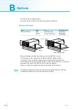
Removing the handle and feet
1
Pull up the handle cover (two
locations).
2
Unfasten the two M4 flat head
screws, and remove the
entire handle.
3
Loosen the screws to remove
the rubber feet (in four loca-
tions).
Power cord
This is the power cord that is used to
connect the product to the AC line (not
CE compliant).
J1/ J2 connector plug kit OP01-PWR-01
A plug kit for externally controlling the
PWR-01 through the J1/ J2 connector.
Adapter cable (RD-8P/9P)
An adapter cable for connecting a D-sub 9-pin
RS232C cable to the product.
Safety plugs
Plugs for connecting to the front-panel output terminals. There are two types.
Rubber feet
(four locations)
Screw
(four locations)
Four M3 screws
Maximum depth:
5 mm
Collar
(four locations)
Bracket
Handle
Cover
M4 flat head screw
(M4x8)
AC5.5-3P3M-M4C-VCTF
For the 1
200 W model
30 pin pieces
Housing for the J1 connector
and J2 connector, 1 piece each
TL41
(screw connection type)
Red and black,
one set each
TL42
(solder connection type)
Red and black,
one set each
Summary of Contents for PWR1201H
Page 7: ...PWR 01 7 This page is intentionally blank ...
Page 12: ...12 PWR 01 This page is intentionally blank ...
Page 74: ...74 PWR 01 This page is intentionally blank ...
Page 100: ...100 PWR 01 This page is intentionally blank ...
Page 112: ...112 PWR 01 This page is intentionally blank ...
Page 113: ...Maintenance This chapter explains how to perform cali bration ...
Page 134: ...134 PWR 01 This page is intentionally blank ...
Page 135: ...Appendix A Factory Default Settings B Options C Troubleshooting ...
Page 144: ...144 PWR 01 ...


