54
PWR-01
CONFIG Settings
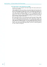
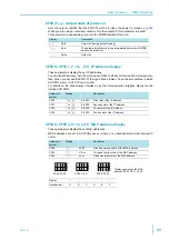
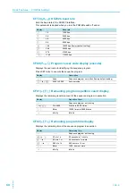
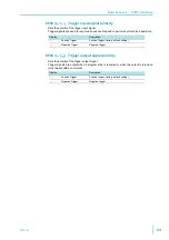
Use the CONFIG settings to set the PWR-01 system configuration. You can set and display
the following parameters in the CONFIG settings.
Effect:
●
indicates that the parameter is affected when the panel settings are reset (CF00).
■
indicates that the parameter may be affected when the LAN interface settings are reset
(CF60:
LCI
/
DEF
).
Note:
○
indicates that the change is immediately applied
△
indicates that the change is applied the next time the power is turned on
◇
indicates that the change is applied when CF60:
APPL
is executed
Display
switching
Parameter
number
Mnemonic
Setting/ display
Effect
Note
Basic
CF00
RSE
Reset
Resets the panel settings
—
○
CF01
1
BLE
Bleeder
Sets the bleeder circuit
—
○
CF02
PRIO
Priority
Output-on startup state
—
○
CF03
VIR
V.I.R
Internal resistance setting (VIR)
●
○
CF04
SS.C.R
S.Start CCrise
Soft start time (CC mode)
●
○
CF05
SS.C.F
S.Stop CCfall
Soft stop time (CC mode)
●
○
CF06
SS.V.R
S.Start CVrise
Soft start time (CV mode)
●
○
CF07
SS.V.F
S.Stop CVfall
Soft stop time (CV mode)
●
○
CF08
ON.D
On delay
Output-on delay setting
●
○
CF09
OFF.D
Off delay
Output-off delay setting
●
○
CF10
E.CC
Ext. CC
CC control using an external voltage/ external resistance
●
○
CF11
E.CV
Ext. CV
CV control using an external voltage/ external resistance
●
○
CF12
E.RNG
Control range
CV/ CC control range
—
○
CF13
M.RNG
Monitor range
Voltage/ Current monitor output range
—
○
CF14
E.OUT
Ext. on/ off
External control for turning output on/ off
●
○
CF15
E.LOG
Ext. logic
External control logic for turning output on/ off
—
○
CF16
STS.C
Stat. CC. pol
CC status signal polarity
—
○
CF17
STS.V
Stat. CV. pol
CV status signal polarity
—
○
CF18
STS.O
Stat. Output. pol
Output status signal polarity
—
○
CF19
STS.A
Stat. Alarm. pol
Protection function/ alarm status signal polarity
—
○
Alarm
CF20
A.RCV
Alarm recovery
Output when AC-FAIL protection is released
—
△
CF21
WDOG
Watchdog
Communication monitoring (WATCHDOG) timer
—
○
CF22
CC.LA
CC limit auto
Current setting limit
●
○
CF23
CV.LA
CV limit auto
Voltage setting limit
●
○
CF24
OC.DL
OCP delay
Detection time of OCP activation
—
○
Usability
CF30
SC1
Short cut 1
CONFIG parameter shortcut registration (SC1)
—
○
CF31
SC2
Short cut 2
CONFIG parameter shortcut registration (SC2)
—
○
CF32
SC3
Short cut 3
CONFIG parameter shortcut registration (SC3)
—
○
CF33
BEEP
Beep
Buzzer on/ off
—
○
CF34
BRI
Brightness
Panel display brightness
—
○
CF35
AMTR
Ammeter
Slave unit display during master-slave parallel operation
—
○
System
CF40
LAN
LAN
LAN interface setting
■
2
△
CF41
USB
USB
USB interface setting
—
△
CF42
232
RS232C
RS232C interface setting
—
△
CF43
TRAC
Trace
SCPI communication error display
—
○
CF44
PARA
Parallel
Master-slave parallel operation
—
△
CF45
PON
Power on
Output state at power-on
—
△
Summary of Contents for PWR1201H
Page 7: ...PWR 01 7 This page is intentionally blank ...
Page 12: ...12 PWR 01 This page is intentionally blank ...
Page 74: ...74 PWR 01 This page is intentionally blank ...
Page 100: ...100 PWR 01 This page is intentionally blank ...
Page 112: ...112 PWR 01 This page is intentionally blank ...
Page 113: ...Maintenance This chapter explains how to perform cali bration ...
Page 134: ...134 PWR 01 This page is intentionally blank ...
Page 135: ...Appendix A Factory Default Settings B Options C Troubleshooting ...
Page 144: ...144 PWR 01 ...


