TOS9213S/ TOS9213AS
6-5
6.2.1
Specifications for the SIGNAL I/O connector
■
Input signal
Low active control input
High-level input voltage:
11
V
to 15
V
Low-level input voltage:
0
V
to 4
V
Low-level AC current:
Maximum -5 mA
Input interval:
Minimum 5 ms
■
Output signal
Open collector output
Output withstanding voltage: 30
V
DC
Output saturation voltage : Approximately 1.1
V
(25 °C)
Maximum output current : 400 mA (TOTAL)
■
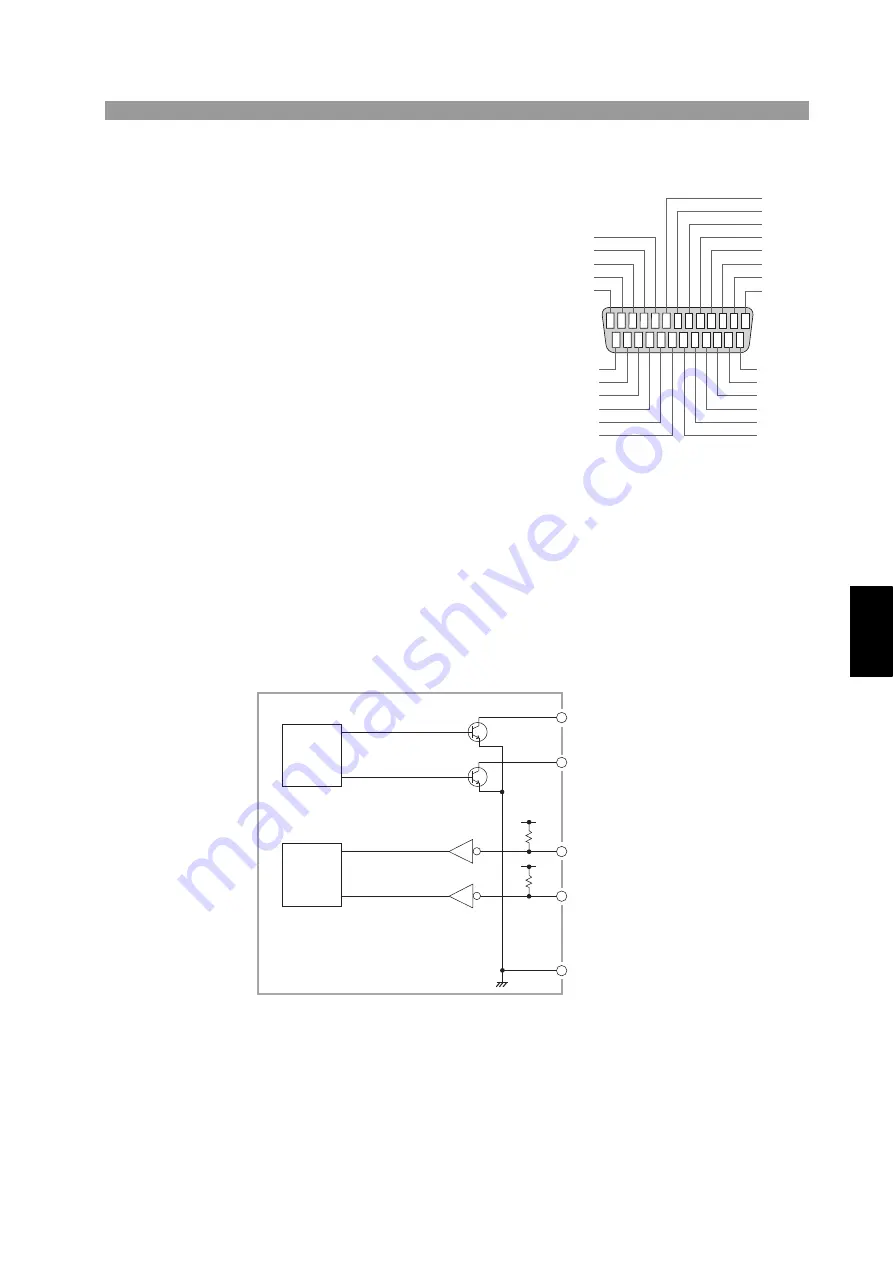
Internal configuration
The same common line is used for the input signal circuit and the output signal cir-
cuit.
The input signal circuit is pulled up to +12
V
. Therefore, opening the input terminal
is equivalent to inputting a high-level signal.
Fig.6-4
Internal config
u
ration of the SIG
N
AL I/O
b
lock
9 8 7 6 5 4 3 2 1
13 12 11 10
19 18 17 16 15 14
24 23 22 21 20
25
PM7
PM6
PM5
PM4
PM3
PM2
PM1
PM0
H.V ON
TEST
PASS
U FAIL
L FAIL
READY
STB
MODE
MODE1
N.C
COM
COM
+24V
ENABLE
STOP
START
PROTECTION
Fig.6-3
SIG
N
AL I/O pin assignment
•
•
•
•
•
•
Output-
signal
control
block
Input-
signal
control
block
COM
Output signal 1
Output signal 2
Input signal 1
Input signal 2
+12V
+12V


