7-4
TOS9213S/ TOS9213AS
7.2
RS-232C Interface
7.2.1
Connecting the RS-232C cable
Turn off all POWER switches on the TOS9200 and other devices that are part of the
RS-232C system.
Connect the RS-232C cable to the RS-232C connector on the rear panel of the tes-
ter.
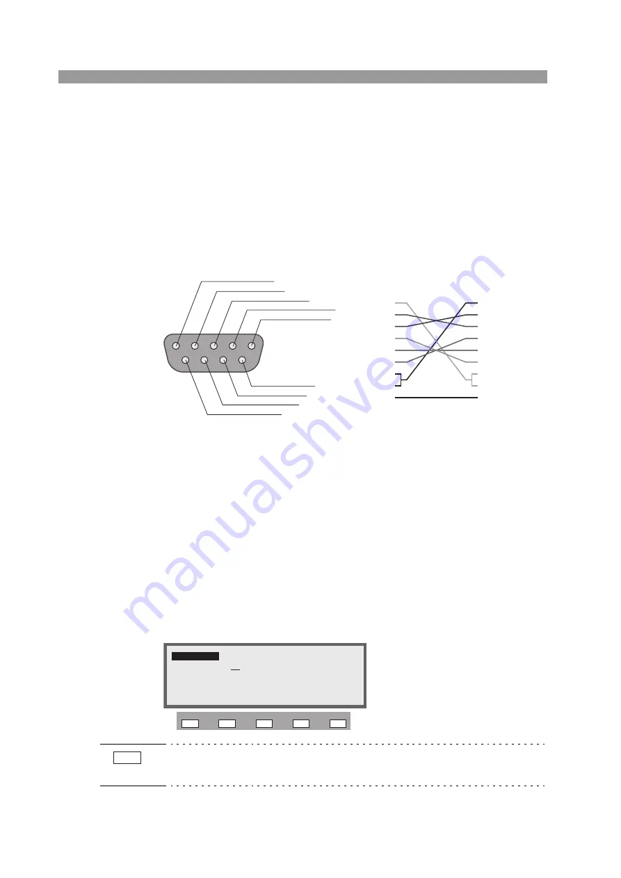
As the RS-232C cable, use an AT-type 9-pin D-SUB female-female cross cable.
Fig.7-1 AT-type 9-pin connector
7.2.2
RS-232C settings
To use an RS-232C interface, the settings specified below must be made.
•
RS-232C interface communication speed
•
RS-232C interface data
•
RS-232C interface parity
•
RS-232C interface stop bit
To make settings, use the Interface Settings screen.
To display the Interface Settings screen (INTERFACE), press the SHIFT + SYS-
TEM(I/F) keys. The SYSTEM(I/F) key will then light up.
• When the interface settings are changed, they become valid after the tester is
restarted.
1: CD (carrier detection)
2: RXD (received data)
3: TXD (transmitted data)
4: DTR (data terminal ready)
5: GND (signal ground)
6: DSR (data set ready)
7: RTS: (request to send)
8: CTS: (clear to send)
9: RI (ring indicator)
On the tester
1
2
3
4
5
6
7
8
9
1
2
3
4
5
6
7
8
9
9-pin D-SUB female
9-pin D-SUB female
Example of a cross cable
GPIB SPEED DATA
PARITY STOP
INTERFACE
INTERFACE
GPIB ADDRESS : 4
SPEED : 19200
PARITY : NONE
DATA
: 8bit
STOP
: 2bit
F1 F2 F3 F4 F5
NOTE


