7-56
TOS9213S/ TOS9213AS
7.5
Registers
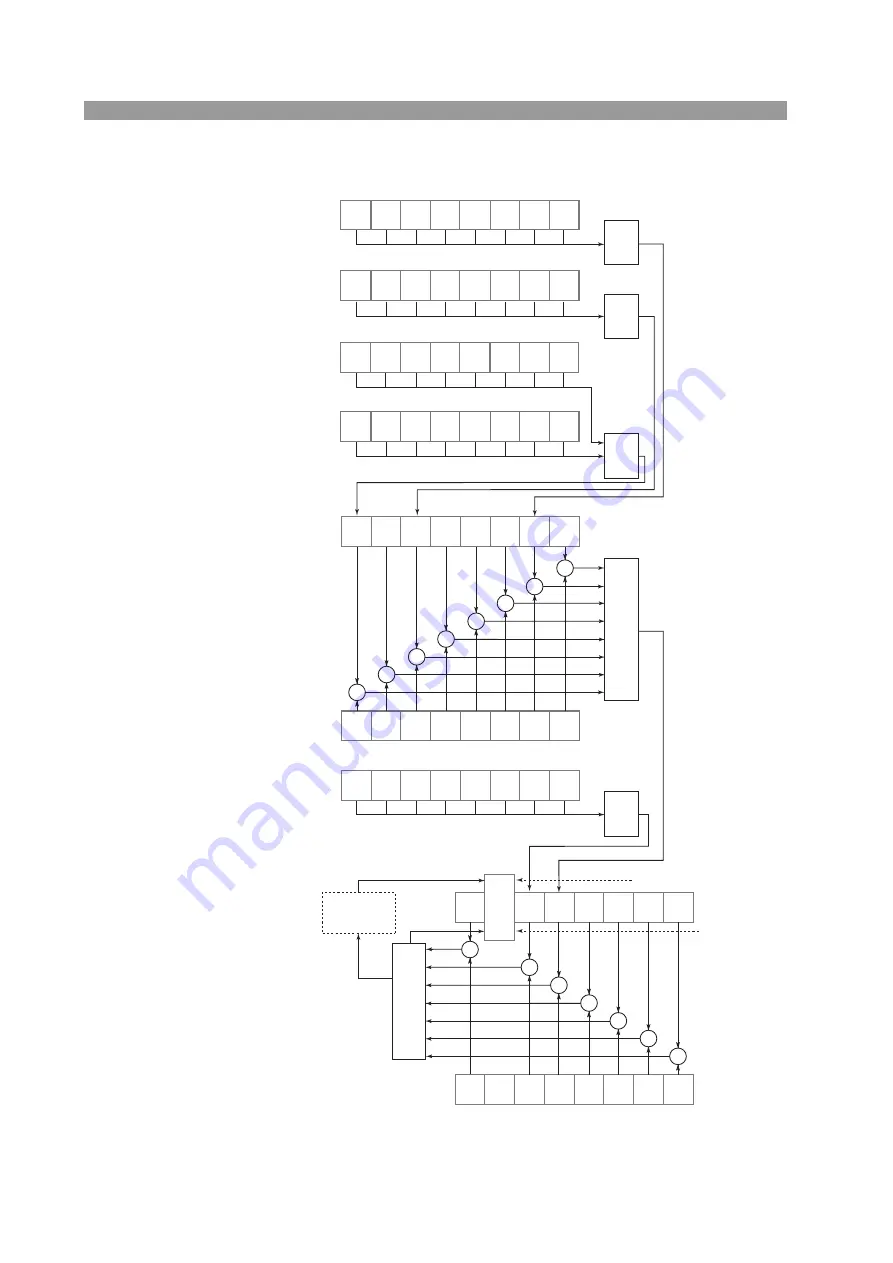
Fig.7-6
Str
u
ct
u
re of stat
u
s data
Issuance of a
service request
7
RQS
MSS
ESB DSB
ESB DSB
Logical
sum
Logical
sum
Device-status enable register
Event status register
Logical
sum
Logical
sum
Logical
sum
Logical
sum
Read by
*STB?
Service-request
enable register
This register is set
by *SRE and read
by *SRE?.
(Initial value: 70H)
Read by DSR?
Read by DSE?
(initial value:
80H)
Read by *ESR?
Status byte
register
7
6
7
6
CME
EXE
3
2
1
0
3
2
1
0
3
2
1
0
HV ON TEST
FAIL
STOP
PROT
PASS
READY
INV
SET
Protection register 2
Invalid-setting register
Read by PROT?
Read by INV?
7
6
TOS62
PROT
TOS62
COMM
REN
SCAN INTER
LOCK
REM IO
10%
50V
100/200
Fail register
Read by FAIL?
7
6
5
4
5
3
UPPER
FAIL
LOWER
FAIL
CONTACT
FAIL
UP
≤
LOW
OVER
55W
OVER
1.1mA
*1
Read by serial polling
HV ON TEST
FAIL
STOP
PROT
PASS
READY
INV
SET
&
&
&
&
&
&
&
&
&
&
&
&
&
&
&
Device status register
Invalid Setting
CME (Command Error): Syntax error, data error,
or out-of-range error
EXE (Execution Error):
When an invalid message has
been
received
FREQ command during the test, etc.
Dvice Status Byte
Event Status Byte
Protection register 1
Read by PROT?
7
6
5
1
LVP
OCP
OVER
LOAD
WAIT
TIME
SCANNER
CHANNEL
OHP
Protection register 1
OVER LOAD: Over 55 W
LVP (Low Volt): Over Crrent
OCP: Current Sensor
OHP: Over Heat
Protection register 2
TOS62 PROT: TOS6200 Protection
TOS62 COMM: TOS6200 Communication Error
REN: Remote Enable
REM IO: Remote In/Out
SCAN: Scanner In/Out
INTERLOCK: Interlock
10%50V: Volt setting
100/200: Select 100/200
*1
For TOS9213AS, “Over 0.11 mA”
when the test voltage setting exceeds 1020 V.


