background image


11 


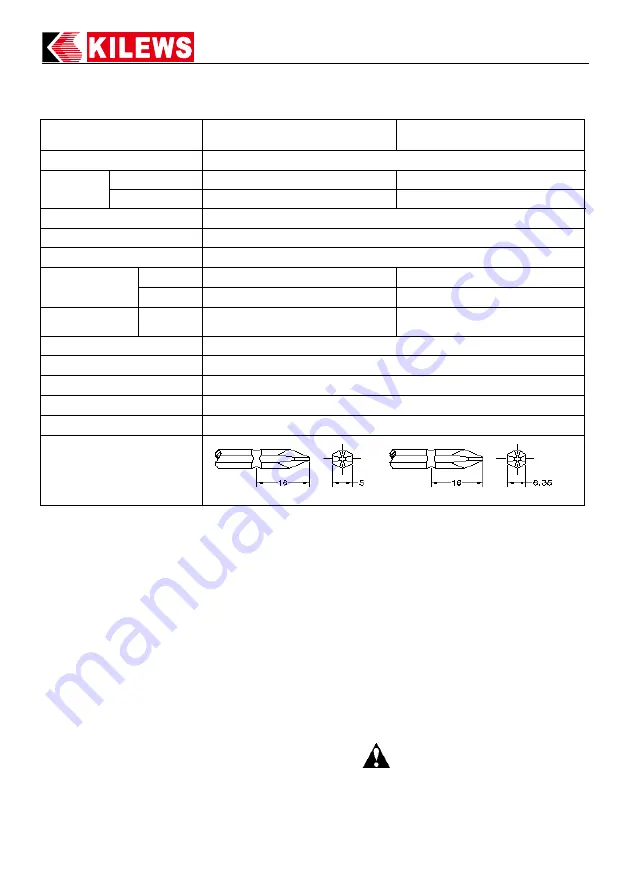
Specifications 

* 1N.m=10.2Kgf.cm    1N.m=8.85Lbf.in 

  Bits Code ~ 

B: Hex 6.35mm


Accessory ~

it no.

No.2

....

Bit use in dia 3.0~4.0mm screw 


PTA-BS12/ PTA-BS12S1


with BIT            1# & 2#       1 Pcs. Each. 


CAUTION 

SAVE THE INSTRUCTIONS 

DO NOT DESTROY 


MODEL 

SKC-PTA-BS12


SKC-PTA-BS12S1


INPUT VOLTAGE(DC) 

DC 7.2V 

TORQUE 

(N.m) 

hard joints   

0.2-1.2


0.2-1.2


soft joints 80%


0.2-0.96


0.2-0.96


Torque accuracy (%) 

±3% 

Torque adjustment 

Stepless 

Duty cycle 

1.0s ON 3.0s OFF 

Unloaded Speed 

  (min

-1 

)±10% 

HI 

1000


500


LO 

700


350


Screw size (mm)  Machine 

screw 

1.6~3.0 

1.6~3.0


Weight (g) 

530kg (w/o battery) 

Length (mm) 

225mm (w/o battery) 

Model of Suspension Rack 

KH-5


Applicable battery 

SKC-LB0725S


Applicable charger station 

SKC-P25W


Applicable Bit type 


HEX 5mm,                      HEX 6.35mm     

Summary of Contents for SKC-PTA-BS12

Page 1: ...al Cordless Brushless Power Torque Screwdrivers Series OPERATION AND MAINTENANCE MANUAL KILEWS INDUSTRIAL CO LTD http www kilews com Y2F228A E 001 Rechargeable TYPE Automatic Brushless Series SKC PTA BS12 SKC PTA BS12S1 ...

Page 2: ......

Page 3: ...refers to your main operated appliance Icon Instructions 1 2 3 4 1 2 3 4 5 6 7 8 9 1 Read instruction manual 6 Do not operate in an explosive atmosphere 2 Observe caution and safety notes 7 Do not disassemble 3 Recyclable 8 Forbid to throw away 4 For indoor use only 9 CE certification 5 Do not expose to wet or rain conditions Accessories Item Quantity Unit Manual 1 PCS Driver hook 1 PCS Bit 2 PCS ...

Page 4: ...ing 6 Dress properly Do not wear loose clothing or jewels while operating the tool to avoid the danger of trapping 7 By using the device correctly make sure to hold it firmly with two hands in place before starting the trigger 8 When using the electrical power tool take into account the auxiliary handle or waist hook is advantage of working conditions On the contrary the purposes of the waist hook...

Page 5: ...tructions in this manual KILEWS is not responsible for any personal injury that might cause of disobeying the safety advices 18 Use a safety device Wear protective earmuffs to reduce personal injury Noise The typical A weighted noise level acc To EN62841 2 2 Sound pressure level LpA 53 6 dB A Sound power level LwA 64 6 dB A Vibration The vibration total valoue acc EN62841 2 2 Vibration emission va...

Page 6: ...ble the device it may result in poor performance or danger of injury the warranty applies only to initial package 3 Do not repair the device with other than genuine KILEWS replacement parts may result in poor performance or danger of injury the warranty will be considered void 4 temperature between 0 C 35 C would be an ideal condition of carrying out the tasks on the device Operating Instructions ...

Page 7: ...move Battery Steps 1 Take screwdriver and battery 1 Press the release button and take it out of the Device 2 Insert the rechargeable battery into the device follow by the arrow as showing 2 Follow the arrow direction 3 Assembled completely 3 Removed completely Battery Release Button ...

Page 8: ...n Function Name Table No Description No Description 1 Trigger Switch 5 Torque Fixing Ring Coupler 2 Forward Reverse Lever 6 S Waist Hook 3 Bit Sleeve 7 OK NG Power Hi Lo Indicating Light 4 Torque Fixing Ring 8 battery 8 1 6 3 7 2 5 4 ...

Page 9: ...showing always set the switch to neutral position when the screwdriver is not being used Forward screw Reverse unscrew 2 2 Hi Lo to change the speed of rechargeable screwdriver push Forward Reverse lever to the middle position release the switch for about 0 5 second and press trigger switch for 5 seconds then there will be a short beep sound to adjust the position 1 It represents Hi position when ...

Page 10: ...orque output by turning torque adjust ring clock wise 0 printed on the torque adjust ring indicates the minimum torque for setting and 8 for the maximum torque setting Do not turn torque adjust ring lower than 0 or higher than 8 to avoid torque adjust ring getting stuck with clutch 5 Coupler 5 1 Coupler Fixed upside underside housing and clutch 6 Driver Hook It is convenient for the production lin...

Page 11: ...ect the battery power when the motor and PCB temperature protection are activated 7 2 Temperature Protection The red indicating light flashes and beep sounds 9 times 7 3 Sleep Power Saving Mode It will enter sleep mode when the screwdriver stopped for about 5 seconds press the lever can wake up sleep The power will be cut off when sleep more than 24 seconds press the switch can restore power Signa...

Page 12: ... 10 When adjusting the torque for safety purpose should stop the screwdriver completely and set the switch to neutral position It could prevent the user from turning the tool on accidentally 11 During operation the switch has been changed accidentally that the device will enable its self protecting mode which is power off Re start the tool when this happen 12 Each operational torque setting using ...

Page 13: ...INPUT VOLTAGE DC DC 7 2V TORQUE N m hard joints 0 2 1 2 0 2 1 2 soft joints 80 0 2 0 96 0 2 0 96 Torque accuracy 3 Torque adjustment Stepless Duty cycle 1 0s ON 3 0s OFF Unloaded Speed min 1 10 HI 1000 500 LO 700 350 Screw size mm Machine screw 1 6 3 0 1 6 3 0 Weight g 530kg w o battery Length mm 225mm w o battery Model of Suspension Rack KH 5 Applicable battery SKC LB0725S Applicable charger stat...

Page 14: ...e values However the clamping torque of screw itself is different form type size material of the screw and the material of its mating part Use it as standard to obtain an appropriate clamping torque 6 The Return torque method in which once clamped screw is returned with torque wrench or the like is available as one of torque control methods however note that the measured values by the return torqu...

Reviews: