background image


Centauri Energy Server 

 User Manual                        Model Number -GF-80000-360Vdc-380Vac-3/3 

This manual is subject to change without notice and at the sole discretion of Kilowatt Labs, Inc.


Kilowatt Labs, Inc. | 

www.kilowattlabs.com 


46 


The following table lists the charge current values of 80KW series 3-phase hybrid solar inverter 

system that can be set via the monitor panel. 

Capacity   Max. value 

Default value 

Min. value 

80KW 

300 A 

15 A 

5 A 


Battery Type (Reserved option) Settings:


 Click the 

Battery Type

 button and select the 

Lead Acid

 or 

Lithium

 to confirm the operation. 


Number of cells settings (fine tuning setting):


Tap “Number of Cells” and input the number of battery cells in the system (this system calculates the 

number of cells according to 2V/3.2V cell standard, and the number of cells is 180/114); the settable 

range for lead acid battery is 166-182 cells, and range for lithium battery is 103-

116 cells; tap “OK” to 

confirm execution. 


Temperature Configuration Settings:


Tap “Temperature Compensation” to enter (the default setting of the system is 2mV/°C, the engineer 

can  select  an  appropriate  parameter  according  to  the  battery's  characteristic  requirements);  the 

settable range is 0mV/°C-

5mV/°C; tap “OK” to execute (When a temperature sensor is not connected, 

the system will perform compensation according to the ambient temperature). 


DOD (depth of discharge) Voltage Settings:


Tap “DOD Voltage” to enter. The depth of discharge represents power supply priority, battery test end 

point and battery low voltage alarm point; the system default lead-acid battery DOD voltage point is 

1.89V from March to October and 2.0V from November; settable range is 1.85V-2.20V; lithium battery 

DOD voltage point is 2.80V, and the settable range is 2.80V-3.47

V. Click “


” to confirm execution.


EOD (end of discharge) Voltage Setting:


Click 

EOD

 and enter setting interface. System default value is 1.75V and set range is 1.58-2.00V; the 

EOD voltage point of lithium battery is 2.50V, and the settable range is 2.30V-3. 15V.Click 


 to 

activate. 


Note:  
The DOD voltage set must be greater than the EOD voltage to be effective. 


Summary of Contents for GF-80000-360Vdc-380Vac-3/3

Page 1: ...CENTAURI ENERGY SERVER User Manual Model number GF 80000 360Vdc 380Vac 3 3 Version 1 0 Release Date May 2020 Author Mamoona Khalid...

Page 2: ...ity power supply featuring stable voltage and frequency even in the cases of a sudden change of AC input voltage and AC frequency over under voltage Legal Provisions No part of this User Manual Manual...

Page 3: ...module panel indicators and alarm warnings 20 3 5 Introduction of Buttons 21 3 5 1 Description of Selection Button Function 21 3 5 2 Description of Function Buttons 21 3 6 Introduction of Breaker 22...

Page 4: ...ance Bypass Operation 42 5 4 1 Precautions 42 5 4 2 Entering Service Mode 43 5 5 System Settings 44 5 5 1 Advanced Setup 44 5 5 1 1 System Mode settings 44 5 5 1 2 PV Auto Power ON Setting 45 5 5 1 3...

Page 5: ...without notice and at the sole discretion of Kilowatt Labs Inc Kilowatt Labs Inc www kilowattlabs com 5 6 4 System Failure 53 7 Maintenance and Troubleshooting 54 7 1 Preventive Maintenance 54 7 2 Mai...

Page 6: ...ystem Control Panel 13 Fig 4 Description of Touch Screen 15 Fig 5 Schematic Diagram of System Installation 27 Fig 6 Schematic Diagram of System Handling 28 Fig 7 Signal Interface of Remote Control 37...

Page 7: ...Menu Icon of Touch Screen 17 Table 5 Description of Button Symbol of Touch Screen 18 Table 6 System LED and Alarm 1 19 Table 7 System LED and Alarm 2 20 Table 8 Description of Selection Buttons 21 Ta...

Page 8: ...ersonnel After the Energy Server is turned OFF its voltage may be still high for a long time please do not open the cabinet because it may cause an electric shock The Manual Bypass switch is used for...

Page 9: ...of Kilowatt Labs Inc Kilowatt Labs Inc www kilowattlabs com 9 In locations with unusually high or low temperatures above 40o C or below 0o C or high humidity 90 Warning 1 The Energy Server must be re...

Page 10: ...ange without notice and at the sole discretion of Kilowatt Labs Inc Kilowatt Labs Inc www kilowattlabs com 10 2 Energy Server Overview 2 1 Part Number 1 Isolated Off Grid Type 2 Capacity of Energy Ser...

Page 11: ...aic power generation system mainly consists of the PV Panels combiner box Energy Server Battery and Load The solar energy of the PV panels is sent to the combiner after converging solar energy is sent...

Page 12: ...onverted by a PV switch through MPPT power module to supply to the battery and DC bus The inverter module converts the DC power of DC bus to pure AC power free from the mains interference In the event...

Page 13: ...r Control 3 1 Control Display Panel 80KW three phase off grid Energy Server can control the off grid inverter and query all the input and output parameters battery status power generation event and al...

Page 14: ...ontrol touch screen control mode Press Up and Down buttons to move the cursor Press the Enter button to execute an operation Table 2 Symbols Function Button symbols Names Function INV ON Power ON butt...

Page 15: ...on Menu Name Menu Items Definition Input Parameters Line Voltage V Rectifier input line voltage Current A Rectifier input current Frequency Hz Rectifier Input frequency Power factor Rectifier Input po...

Page 16: ...ed load percentage Parallel parameters Apparent Power KVA S out Apparent power Active power KW P out Active power Stand alone system with no parallel data When the Energy Sever is set to stand alone i...

Page 17: ...urrent Module Status Current module status Table 4a Description of Menu Icon of touch screen Button Icons Name Functions Settings Press this button to enter system settings ON OFF Press this button to...

Page 18: ...button to return to the previous menu of the directory Page down button Press this button to page down Page up button Press this button to page up Left shift button Press this button to move the curs...

Page 19: ...eep once per 4 seconds Red light flashing once per 2 seconds Battery test Beep once per 2 seconds Green light steady ON No fault No beep Table 6 System LED and Alarm 1 LED Red light steady ON Green li...

Page 20: ...e Battery test under voltage Table 7 System LED and Alarm 2 3 4 MPPT module panel indicators and alarm warnings Fig 5 MPPT Module Panel Indicators and Alarm Warnings MPPT module LED indicator Off Stea...

Page 21: ...can move the cursor through pressing or button to choose the required control button and then press the button for confirmation 3 5 2 Description of Function Buttons Button Symbols Name Functions INV...

Page 22: ...bypass input by switching ON this button OUTPUT Output switch Turning ON the output breaker will make a connection between the load and the system static switch BYPASS Bypass switch TURN ON the Bypas...

Page 23: ...PV 4 Input terminals pole AC INPUT R line S line and T line of rectifier input terminal BYPASS INPUT R line S line T and N line of bypass input terminal AC OUTPUT R line S line T line and N line of sy...

Page 24: ...Description of Remote Control Signal Input 3 9 Description of Output Signal at System Dry Contact English Name Chinese name Normally Closed Nodes Normally Opened Nodes FAN FAULT Fan fault Fan normal F...

Page 25: ...site must be provided with the professional engineers authorized by the company for the guidance of installation Ground the Energy Sever properly and turn OFF all switches before making electrical con...

Page 26: ...tion on the internal or external surface of the Energy Sever and the battery If there is any damage do not install or use the system please notify the carrier for disposal immediately Check the techni...

Page 27: ...fan should be installed to ensure sufficient air flow in the room so that the equipment gets full heat dissipation in case of the rise in room temperature It is best to be equipped with A C system 2...

Page 28: ...ews if a forklift is used to lift insert the forks of forklift into the gap between the pallet and the bottom of the cabinet refer to the reference point of the cabinet s center of gravity Lift the ca...

Page 29: ...ensure that the distance between the battery and the Energy Sever is shortest as much as possible Sirius Module Do not charge the Module when the temperature is below 30o C Do not charge the Module w...

Page 30: ...d capacity iii The ambient temperature iv Physical support media The qualified installation engineers should select suitable cable for connection according to local related standards and table 14 The...

Page 31: ...of Power Cable 4 10 Energy Server Wiring Description 4 10 1 AC Mains Wiring Method Off grid solar inverter applies the lower wiring method Before wiring open the front door with the key supplied with...

Page 32: ...BATTERY PV 1 PV 2 PV 3 PV 4 PV 5 PV 6 PV 7 PV 8 PV INPUT PV 1 PV 2 PV 3 PV 4 PV 5 PV 6 PV 7 PV 8 PV INPUT Signs Functions PV INPUT PV 1 n input terminals pole PV INPUT PV 1 n input terminals pole AC I...

Page 33: ...dc 380Vac 3 3 This manual is subject to change without notice and at the sole discretion of Kilowatt Labs Inc Kilowatt Labs Inc www kilowattlabs com 33 Fig 8 80KW inverter System Two way mains Wiring...

Page 34: ...em After equipment is completely positioned the input terminals of each Energy Server are connected together the output terminals are connected together The wiring diagram is shown below Fig 9 Paralle...

Page 35: ...phase sequence and then fasten them 5 Connect the R S T and N ports of the AC INPUT rectifier input terminal board with the corresponding R S T and N ports of the external BYP INPUT power switch or b...

Page 36: ...are completely shut down and the external switches of rectifier power supply the bypass power supply and the battery pack are switched on and then use the multimeter to test and make sure that the vo...

Page 37: ...nsing Perform charging compensation by battery temperature coefficient BAT TEST Battery self test Short circuit 0 2 s The Energy Server performs battery test INV ON Energy Server power ON In standby m...

Page 38: ...mally closed contact 4 13 Parallel Signal Port Each Energy Server has four parallel cable ports two are DB25 and other two are DB9 In the parallel system when connecting parallel cables of DB25 as wel...

Page 39: ...parts for the user Only the maintenance support personnel authorized by the company can open the protective cover plate of Energy Server 5 1 2 Power ON Steps 1 Switch ON the output switch of the batte...

Page 40: ...e Energy Server 2 Switch OFF the output switch 3 Switch OFF the switches of PV n in turn 4 Switch OFF the RECTIFIER and BYPASS switches of the Energy Sever 5 Switch OFF the DC START switch of the Ener...

Page 41: ...l system are all closed and the output terminals are all connected together 5 1 5 Power OFF Procedures Parallel system 1 Turn OFF all loads of the total output of parallel system 2 Tap the ON OFF icon...

Page 42: ...gy Sever overload being more than or equal to 150 DC BUS instantaneous overvoltage abnormal protection etc please confirm that the fault has disappeared according to the prompt of the alarm informatio...

Page 43: ...switch to turn it ON at this point the maintenance bypass power supply and inverter static bypass power supply are in parallel to power the load 3 Press the OFF button on the panel and then click OK b...

Page 44: ...press button in the main interface to enter INV Settings Go to Manual Bypass interface successively to select OFF option and click YES button At this point the maintenance steps have been completed a...

Page 45: ...ing The battery parameter settings will affect the reliability and security of the system and may cause damage to the battery Please be sure to enter the actual data of the system to ensure the safe u...

Page 46: ...Configuration Settings Tap Temperature Compensation to enter the default setting of the system is 2mV C the engineer can select an appropriate parameter according to the battery s characteristic requ...

Page 47: ...he original user settings will be completely cleared Please conduct the operations above carefully If the operation is necessary be sure to set the relevant parameters according to the requirements of...

Page 48: ...urrent charging 5 5 2 4 Protocol Settings The protocol settings are used to setup the 485 communication protocol The following three items can be set 1 Address It is 1 by default 2 Baud rate It is 240...

Page 49: ...of Kilowatt Labs Inc Kilowatt Labs Inc www kilowattlabs com 49 5 5 2 9 Touch Screen Calibration Touch screen calibration is used to calibrate the center point of the screen When the system is restored...

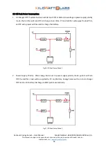
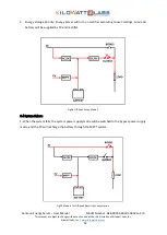
Page 50: ...rmal 1 When PV Power is higher than load power it will supply power to the load first and the extra power will be used to charge the battery In this case if PV charge current is high enough AC will no...

Page 51: ...ils the PV power will support the load first and the extra power will be used to charge the battery Fig 14 AC Abnormal Mode 1 2 When the PV power is less than the load power and AC fails the PV togeth...

Page 52: ...ery low voltage in power supply priority mode the rectifier will turn OFF AC charger in set time PV and rectifier will supply the load first and PV extra power will be used to charge the battery Fig 1...

Page 53: ...53 3 Energy storage priority Energy Server will turn on rectifier according to user settings Load and battery will be supplied by PV and rectifier Fig 18 Off Peak Setup Mode 3 6 4 System failure 1 Wh...

Page 54: ...equency of the battery and the temperature rise Even if the battery is not used its performance will gradually decline therefore it is recommended that one discharge test Make sure the battery test sh...

Page 55: ...to 0 5 1 year 4 With ageing of the battery the performance of the battery gets poor When the battery health drops down to about 80 of the initial value the discharge time decreases accordingly The ba...

Page 56: ...not less than 150 and the overload time is finished or the inverter is shut down for protection Output Over Load The load is more than 105 Get the load shedding to be less than 90 REC Fault After the...

Page 57: ...h the requirements of the Energy Server and whether the switches are in normal operation BYP Phase Abnormal The bypass phase sequence is reverse Adjust any two phases of the system input lines Bypass...

Page 58: ...tton for recovery EPO Press the red button on the panel or conduct the remote EPO operation Remove the remote EPO order and execute the OFF operation steps and then execute the ON steps after the syst...

Page 59: ...k the local authorized technician for service Over Current The power of PV polar plate is too high and there is instant overcurrent Check whether the power of the polar pole confirms to the system rat...

Page 60: ...ates in series PV under voltage Poor illumination Confirm the direction and the pavement gradient of the polar plate MPPT is not detected MPPT shutdown of the communication blackout The MPPT system sh...

Reviews: