Assembly Instruction
Perks
P
ri
n
te
d
in
U
.S
.A
.
©
2
0
0
8
K
im
b
a
ll
In
te
rn
a
ti
o
n
a
l,
In
c
.
T
8
0
0
.4
8
2
.1
8
1
8
F
8
1
2
.4
8
2
.8
3
0
0
Proper product installation, in accordance with these instructions, is the responsibility of the installing agent.
If you have any questions concerning these instructions, please call Kimball Office Customer Service.
Part No. 2066769
Revision A-08
Page 1 of 1
Undersurface Cable Manager
Tools Required
■
#2 Phillips Head Bit
■
Screw Gun
■
Hack Saw
(if cutting to length)
Package Contents
■
12 #8 Panhead Screws
Installation
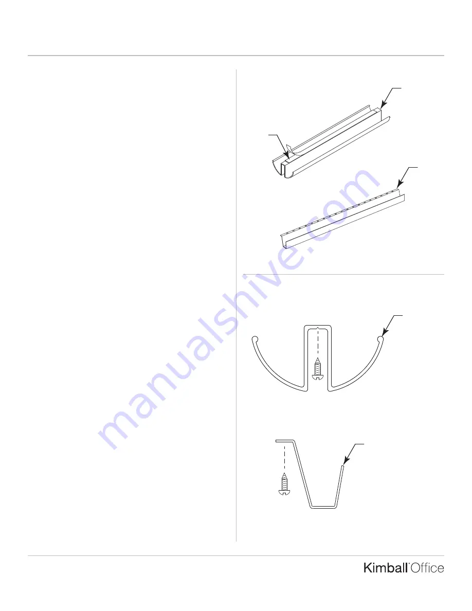
1. Measure the area where the Undersurface Cable Manager
is to be mounted. Mark and cut the cable manager to the
desired length.
2. On “W” shaped cable mananger, peel the protective coating
from the tape strip provided. Position the cable manager in
its desired location and press firmly into place. “U” shaped
cable managers does not come with tape strip. (Figure A).
3. The cable managers can be permanently attached to the
underside of the worksurface using #8 panhead screws
provided. The “W” shape has a V-groove to assist with screw
location. (Figure B).
Figure A
Figure B
Undersurface Cable
Managers
Tape
TM
“W” Shape
“U” Shape
“U” Shape
“W” Shape


