Assembly Instructions
Perks
P
ri
n
te
d
in
U
.S
.A
.
©
2
0
0
8
K
im
b
a
ll
In
te
rn
a
ti
o
n
a
l,
In
c
.
T
8
0
0
.4
8
2
.1
8
1
8
F
8
1
2
.4
8
2
.8
3
0
0
Proper product installation, in accordance with these instructions, is the responsibility of the installing agent.
If you have any questions concerning these instructions, please call Kimball Office Customer Service.
Part No. 2066773
Revision A-08
Page 1 of 1
Power/Data Grommet Insert
Tools Required
■
None
Package Contents
■
1 Power/Data Grommet Insert
General Information
■
The power/data grommet insert can be located in any
worksurface. It is used when it is desirable to have access
to electrical power and telephone/data at the worksurface.
Excess cabling can be routed under the worksurface through
an opening in the metal cap.
■
Check for clearance under worksurface
BEFORE
boring to
avoid brackets, panels or similar interferences.
■
Fits G7 grommet/option on Evoke, Definition, Transcend,
Senator, President, Innsbruck, and Osterley Park.
Installation
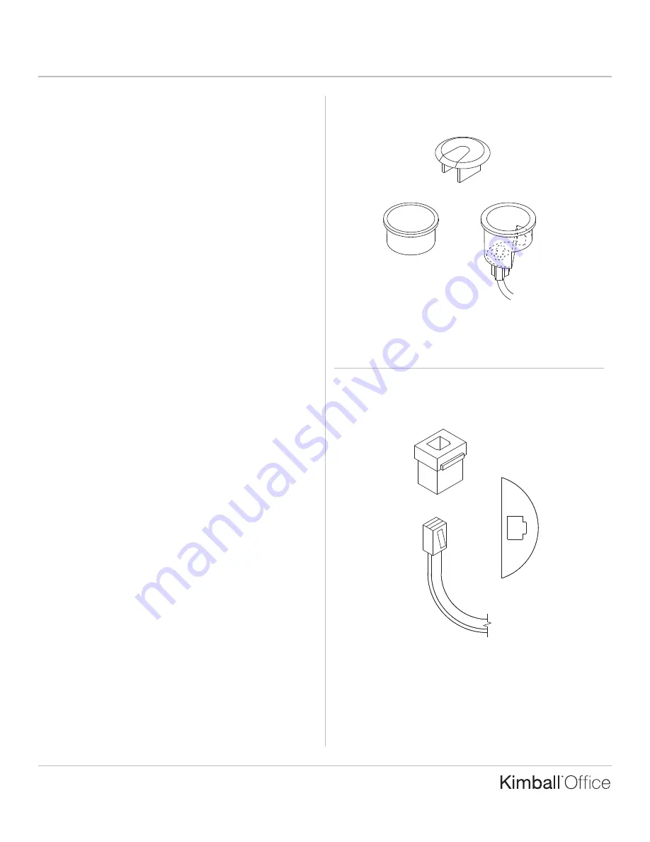
1. If worksurface has existing grommet, remove the plastic
trim ring that came with the metal grommet cap, and
replace it with the power/data grommet insert cup.
(Figure A).
Note:
If worksurface does not contain grommet, refer to
Grommet Installation assembly instructions.
2. A universal knock-out is a feature of the power/data
connector cup. The knock-out will work with the following
data ports:
■
Amp - 1.800.522.6752
■
Panduit - 1.800.777.3300 ex. 1884
(Figure B).
Figure A
Figure B
Data Port
To
telephone
line
Plastic Trim
Ring
Power/Data
Grommet Insert
Metal Grommet Cap
TM


