background image

4 Use of the device

4.1 Display

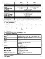
The selected values to display during the configuration with the KILOG software will scroll on the 
screen every 3 seconds.

The display can be activated or deactivated via the KILOG software.

At extreme temperatures, the display can become hardly readable and its display speed can slow 
down at temperatures below 0°C. This has no incidence on the measurement accuracy.

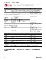
4.2 Function of LEDs

12

Use of the device

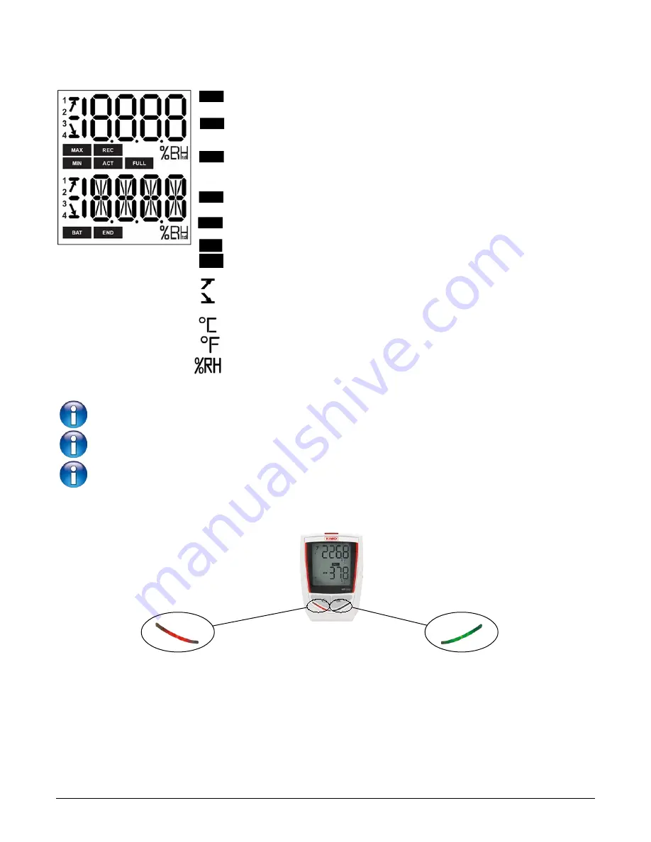
Alarm LED

If the red 

“Alarm”

 LED has been activated, it has 3 states:

- Always OFF:

 no setpoint alarms has been exceeded

- Flashing quickly (5 seconds):

 a threshold is currently 

  exceeded on one channel at least

- Flashing slowly (15 seconds):

 at least one threshold has been 

  exceeded during the dataset

Operating LED

If the green 

“ON”

 LED has been activated, 

it flashes every 10 seconds during the 
recording period.

DATASET is finished.


END

Indicates that one value is being recorded.

It flashes: the DATASET did not start already.


REC

Flashing slowly: DATASET is between 80 and 90% of the storage capacity.

Flashing quickly: DATASET is between 90 and 100% of the storage capacity.

Constant: storage capacity full.

FULL

The displayed values are the maximum/minimum values recorded for the channels displayed.

 MIN

 MAX

Indicates the alarm action type: rising or 

falling action.

Constant: indicates that the batteries have to be replaced.

BAT

ACT

Screen actualisation of measured values.

Indicates the channel number which is 

measuring.

Temperature in °Celsius.

Temperature in °Fahrenheit .

1
2
3
4

Relative humidity

Summary of Contents for KISTOCK 320 Series

Page 1: ...Class 320 KISTOCK KT 320 KCC 320 KP 320 321 KPA 320 KTT 320 USER MANUAL...

Page 2: ......

Page 3: ...bes 10 3 6 Dimensions in mm 11 3 6 1 Devices 11 3 6 2 Wall mount in option 11 3 7 Guarantee period 11 4 Use of the device 12 4 1 Display 12 4 2 Function of LEDs 12 4 3 Function of keys 13 4 3 1 Groups...

Page 4: ...se the protection ensured by the device 1 2 Symbols used For your safety and in order to avoid any damage of the device please follow the procedure described in this user manual and read carefully the...

Page 5: ...dataloggers are ideal for different parameters surveillance temperature hygrometry light current voltage impulsion relative pressure They ensure the traceability in the food industry environment as w...

Page 6: ...the device and the computer is carried out via an USB cable and with the female micro USB connector 2 8 Mounting The class 320 KISTOCK has magnetic mountings so you can fix it easily 6 Presentation of...

Page 7: ...C 0 3 of the reading 0 4 C below 0 C S 0 6 C Setpoints alarm 2 setpoint alarms on each channel Frequency of measurements From 1 second to 24 hours Operating temperature From 40 to 70 C From 20 to 70 C...

Page 8: ...0 to 50 C 0 8 C below 0 C or above 50 C Humidity 2 RH from 5 to 95 15 to 25 C Atm pressure 3 hPa CO2 50 ppm 3 of the reading Temperature 0 4 C from 0 to 50 C 0 8 C below 0 C or above 50 C Humidity 2...

Page 9: ...mmed units The available programmed units for the KT 320 and KTT 320 KISTOCK are the following m s fpm m s C F HR K PSI Pa mmH2O inWg kPa mmHg mbar g Kg bar hPa daPa Ctd Ftd Ctw Ftw kj kg mA A mV V Hz...

Page 10: ...Voltage input cable 0 5 V or 0 10 V KICC Current input cable 0 20 mA or 4 20 mA KICI Pulse input cable Maximal voltage 5 V Type of input TTL frequency counting Maximal frequency 10 kHz Maximum number...

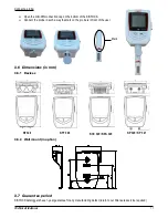
Page 11: ...e mark on the probe is in front of the user 3 6 Dimensions in mm 3 6 1 Devices 3 6 2 Wall mount in option 3 7 Guarantee period KISTOCK dataloggers have 1 year guarantee for any manufacturing defect re...

Page 12: ...15 seconds at least one threshold has been exceeded during the dataset Operating LED If the green ON LED has been activated it flashes every 10 seconds during the recording period DATASET is finished...

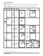
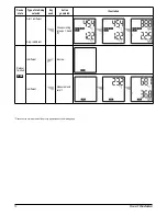
Page 13: ...ated Illustration Waiting for start flashes Start by button Stop indifferent Start of dataset Inactive Start by PC date time Stop indifferent Inactive Start indifferent Stop indifferent Measurements s...

Page 14: ...erated Illustration Start indifferent Stop indifferent Group scrolling groups 1 2 and 3 Dataset finished Indifferent Inactive Indifferent Measurements scroll Please see the summary table of the groups...

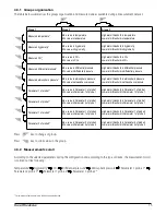
Page 15: ...be 1 Min value in Parameter 1 of probe 1 High alarm threshold in Parameter 1 of probe 1 Low alarm threshold in Parameter 1 of probe 1 Parameter 2 of probe 1 Max value in Parameter 2 of probe 1 Min val...

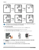
Page 16: ...onnector of the cable to an USB connection on your computer 2 Open the USB cap on the right side of the datalogger 3 Connect the male micro USB connector of the cable to the female micro USB connector...

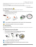
Page 17: ...place the battery hatch and screw it Only use trademark or high quality batteries in order to guarantee the announced autonomy After the battery replacement the device must be reconfigured 6 2 Device...

Page 18: ...e KCC 320 device with the supplied Tygon tube Generate a gas flow of 30 l h Wait for the measurement stabilisation about 2 minutes Check the CO2 values measured by the KCC 320 If these values are not...

Page 19: ...te Results restitution on PC of realised datasets KNT 320 USB micro USB cable which allows to plug your KISTOCK datalogger to your PC CK 50 Neck size hand strap KDC Only the accessories supplied with...

Page 20: ...rdance to guidelines relating to WEEE BE CAREFUL Material damages can happen so please apply the precautionary measures indicated NTang Class 320 Kistock 19 11 18 RCS 24 P rigueux 349 282 095 Non cont...

Reviews: