background image


DACC2000 

User's Manual 


ENG-015 Rev. 1 


Summary of Contents for DACC2000

Page 1: ...DACC2000 User s Manual ENG 015 Rev 1...

Page 2: ...ther express or implied including but not limited to the implied warranties of merchantability or fitness for a particular purpose Information in this publication is subject to change without notice F...

Page 3: ...CONTENTS...

Page 4: ...Accumulator Inputs 2 6 2 2 4 Relay Outputs 2 6 2 2 5 Analog Outputs 2 7 2 2 6 Display connection 2 7 3 0 Communications 3 1 3 1 Port Connections 3 1 3 2 RS 485 3 2 4 0 Operation 4 1 4 1 Internal 4 1...

Page 5: ...CONTENTS...

Page 6: ......

Page 7: ...re the following sections Features Installation Communications Operation Specifications 1 2 Features Full Production Control with PROcontrol Multi run Flow Computer Store and Forward Capability Solar...

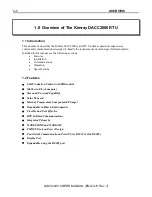
Page 8: ...DACC2000 USER S MANUAL ENG 015 Rev 1...

Page 9: ...UT DISPLAY PWR GND 485 485 0 0 1 1 2 2 3 3 V ACC0 ACC0 GND ACC1 ACC1 V 0 0 V 1 1 V 2 2 V 3 3 0COM 0NO 0NC 1NC 1NO 1COM 2COM 2NO 2NC 3NC 3NO 3COM ANALOG OUT0 GND VOLT CURR VOUT GND BATT GND CHGR GND RA...

Page 10: ...screwdriver 2 1 Power Interconnection This section describes connecting your DACC2000 to the Battery Radio Charging Source and other power devices The power terminal barrier is on a plug in card on th...

Page 11: ...magnitude A recommended noise reduction technique is using shielded twisted pair wiring between the signal source and the DACC2000 termination Twisted pair wire with a minimum of 6 twists per inch wi...

Page 12: ...el JP4 through JP7 are used to connect 250 shunt resistors to each channel for using 4 to 20 mA input signals The resistors are enabled by closing the jumper As long as the jumper is open the resistor...

Page 13: ...sing the jumper shown in Figure 2 3 for the channel Voltage Inputs 1 to 5 volt transmitter signals are connected as shown in Figure 2 3 when the DACC2000 is providing the power for the transmitter The...

Page 14: ...he input is connected between ACC0 and GND Voltage Input Devices The most common type of voltage input device is the relay or switch When open there is no power on the switched side of the device When...

Page 15: ...gure 2 6 The CURR terminal connects to the minus terminal of a device and the VOUT connects to the plus terminal Jumper JP8 must be installed to power the outputs internally ANALOG OUT0 JP8 GND VOLT C...

Page 16: ...00 VOLTAGE OUTPUT CONNECTIONS 2 2 6 Display connection Figure 2 8 shows the connection of the display to the Processor Card The display interface connector is on the top center of the card The Potenti...

Page 17: ...3 1 XMIT XMIT RECEIVE COMM1 KIMRAY DACC2000 RS 485 DIGITAL INPUTS DISPLAY PWR GND 485 485 0 0 1 1 2 2 3 3 COMM2 PERIPH FIGURE 3 1 DACC2000 COMMUNICATIONS PORTS Table 3 1 shows the pinout of the three...

Page 18: ...medium The half duplex wiring of RS 485 requires only a single wire pair to interconnect all stations Termination resistors should be placed at the opposite ends of the system The DACC2000 has an int...

Page 19: ...3 3 COMMUNICATIONS DACC2000 USER S MANUAL ENG 015 Rev 1 KIMRAY DACC2000 PWR GND 485 485 TB1 KIMRAY I O CIM KIMRAY MULTIVARIABLE CIM FIGURE 3 4 DACC2000 AND KIMRAY CIM CONNECTION...

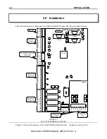
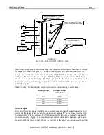
Page 20: ...COMMUNICATIONS 3 4 DACC2000 USER S MANUAL ENG 015 Rev 1...

Page 21: ...lithium battery A battery backed up clock calendar circuit gives the DACC2000 time keeping capability even without primary power The battery is the same as used for protecting the RAM 4 2 Input Outpu...

Page 22: ...nnected to its minus input a current flows from a resistor through an LED and through the optocoupler This provides a signal read by the input circuitry and turns on the LED for the channel 0 0 1 1 2...

Page 23: ...annel 1 is designed for low level inputs and is differentially surge protected by back to back diodes This limits the input voltage to less than 1 V The pulses are then conditioned by special circuitr...

Page 24: ...SED VOLTAGE 110 TO A D FIGURE 4 5 DACC2000 ANALOG OUTPUTS SIMPLIFIED SCHEMATIC 4 2 6 Power Switching The DACC2000 has solid state switches power FET s to control battery charging radio power and auxil...

Page 25: ...GND BATT GND FIGURE 4 6 DACC2000 POWER SWITCHING SIMPLIFIED SCHEMATIC 4 2 7 Display Interface The DACC2000 has a display interface to drive a character display It includes a temperature compensated b...

Page 26: ...the COMM ports by using the RTS signal Whenever the DACC2000 asserts RTS the LED is automatically turned on RXD0 TXD0 VCC GND RI DTR CTS TXD RTS RXD DSR DCD PERIPH LOS 5 9 4 8 3 7 2 6 1 J2 COMM1 GND...

Page 27: ...ity non condensing DIGITAL INPUT Channels 4 Description LED state indicator on each line Compression type terminals Dry contact sense current provided internally or externally High 8V minimum for a vo...

Page 28: ...ttery voltage Charger voltage Compression type terminals 12 bit resolution A D conversion COMMUNICATION Channels 4 Rate 150 to 9600 baud software selectable Connector DB9 on three ports Terminal Barri...

Page 29: ......

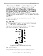
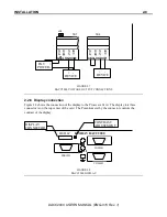
Page 30: ...DACC2000 USER S MANUAL ENG 015 Rev 1 D2KHM DOC 5 19 04...

Reviews: