


2-7
INSTALLATION
DACC2000 USER'S MANUAL (ENG-015 Rev. 1)
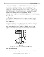
COM terminal is the pole of the relay, NO is the normally open contact and NC the normally
closed contact. Each channel has an LED to indicate when the channel is energized.
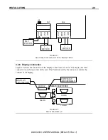
2.2.5 Analog Outputs
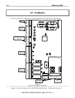
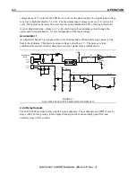
The two optional Analog outputs of the DACC2000 each generate a 4 to 20 mA DC output
(which is normally required for process actuators) or a 1 to 5 volt output. The outputs are
normally powered by the DACC2000 but can be powered from an external source. The analog
output terminations are located along the bottom right edge of the DACC2000 card on TB7 and
TB8 (refer to Figure 2.6). Each channel has four screw terminations lVOUT, CURR,
VOLT and GND.
Current Sinking Outputs
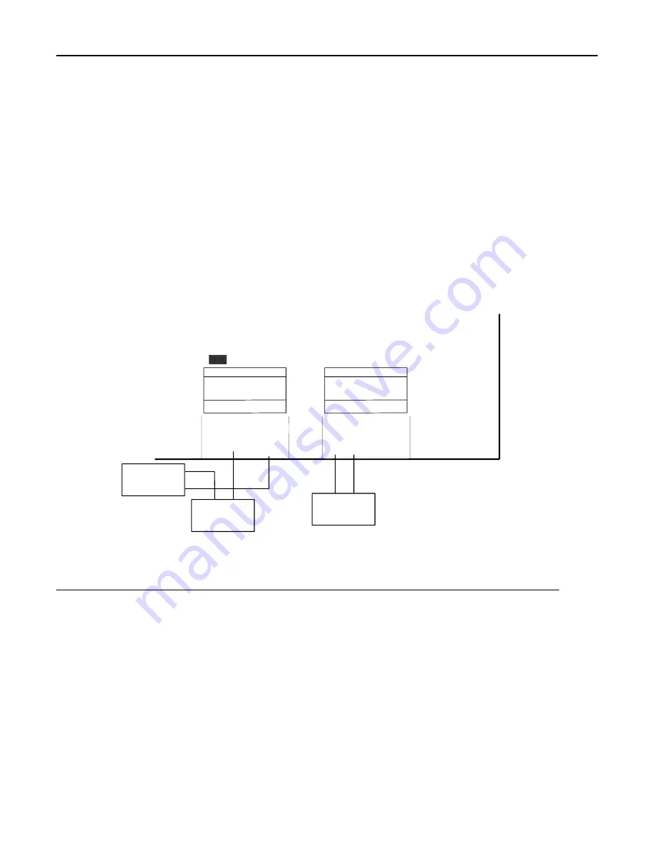
For connecting the current sinking output to a device with the DACC2000 supplying the power,
connect as shown for channel 1 in Figure 2.6. The CURR terminal connects to the minus
terminal of a device and the VOUT connects to the plus terminal. Jumper JP8 must be installed
to power the outputs internally.
ANALOG OUT0
JP8
GND
VO
LT
CURR
VO
U
T
TB7
TB8
ANALOG OUT1
GND
VO
LT
CURR
VO
U
T
+ -
DEVICE
+ -
DEVICE
EXT. +
POWER -
FIGURE 2.6
DACC2000 ANALOG OUTPUT CONNECTIONS
When external power is used, the device's plus terminal is connected to the external power
source and the minus terminal is connected to the CURR terminal of the DACC2000 as
illustrated for Channel 0 in Figure 2.6. The external power source common is connected to the
GND terminal.
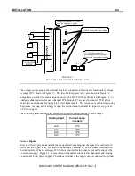
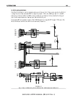
Voltage Outputs
For a voltage output with internally supplied power, connect the minus terminal of the device to
GND, the plus terminal to VOLT and VOUT to CURR as shown in Figure 2.7.
When using externally supplied power, connect as shown for Channel 0 in Figure 2.7. The
minus output of the power source connects to GND and the plus output connects to CURR. The
device is connected for internally supplied power with minus to GND and plus to VOLT.
Summary of Contents for DACC2000
Page 1: ...DACC2000 User s Manual ENG 015 Rev 1...
Page 3: ...CONTENTS...
Page 5: ...CONTENTS...
Page 6: ......
Page 8: ...DACC2000 USER S MANUAL ENG 015 Rev 1...
Page 20: ...COMMUNICATIONS 3 4 DACC2000 USER S MANUAL ENG 015 Rev 1...
Page 29: ......
Page 30: ...DACC2000 USER S MANUAL ENG 015 Rev 1 D2KHM DOC 5 19 04...


