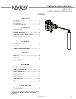
background image

PNEUMATIC LEVEL CONTROLLER

GEN 3

Summary of Contents for GEN 3

Page 1: ...PNEUMATIC LEVEL CONTROLLER GEN 3...

Page 2: ...ade to ensure their accuracy they are not to be construed as warranties for guarantees express or implied regarding Kimray products or services described herein or their use or ap plication All sales...

Page 3: ...ct Switch 5 Left hand right hand conversion 5 INSTALLATION Install Onto Vessel 6 Connections 7 Snap and throttle mode switch 7 OPERATION Start up 8 Calibration 8 Span adjustment 8 MAINTENANCE Paraffin...

Page 4: ...ance information for the product A2 Description The Gen 3 Liquid Level Controller is designed for use in single phase interface liquid control applications The pilot is capable of both Snap mode on of...

Page 5: ...orque Lever Cap Screw Set Screw 1 2 NPT Plug Cap Screw Spring Adjustment Assembly Mount A B C D C E F G Mount Orientation The Gen 3 can be ordered in either Left Hand or Right Hand mount but if you ne...

Page 6: ...leed valve Make sure all pressure is released from vessel and confirm no pressure remains in supply gas instrument air lines Do not install in a location where Max Allowable Working Pressure could be...

Page 7: ...labeled S and plug the remaining S port Connect supply line to filter Use T ports for Vent Supply for Snap Mode Supply for Throttle Mode Installation Vent Connect a Vent Line or Breather Plug to one o...

Page 8: ...uced Operation Snap Mode Direct Acting Fail Closed aka PO valve With the output at 0 psi turn the set point adjustment knob counterclockwise to snap on producing the full output pressure Then turn the...

Page 9: ...be replaced use the Technical Specs document 08 05 1 to determine which part number s are needed and contact your local Kimray authorized store or distributor to order WARNING A leaking controller is...

Page 10: ...Use pliers on stem of actuator to pull out diaphragm assembly Step 8 Clean out all communication holes Pilot Reassembly Step 1 Clean pilot cartridge and install pilot plug small diameter first into t...

Page 11: ...e 11 www kimray com Maintenance Pilot Assembly Pilot Pilot Screw Top Cartridge Cap Upper Diaphragm Assy Booster Spring Pilot Plug O Ring Bottom Cap O Ring O Ring O Ring Booster Pilot Spring Lower Diap...

Page 12: ...m hubs Inspect flanged bearings for wear or damage Remove and discard O rings and back up rings inside hubs Step 9 Inspect shaft for wear or damage Clean out inside of mount Mount Reassembly Step 1 In...

Page 13: ...peration Maintenance Guide 13 www kimray com Maintenance Mount Assembly Back Up Bearing Hub Flanged Bearing Torque Lever Socket Plug Displacer Arm O Ring Gasket Torque Shaft Mount O Ring O Ring Back U...

Page 14: ...and remove from enclosure Step 4 Remove spring adjusting knob from bushing Remove and replace PTFE washer and O ring on spring adjusting knob Spring Assembly Reassembly Step 1 Install spring adjustin...

Page 15: ...hutoff supply pressure to controller and bleed supply line Step 2 Remove the supply line from the filter and remove the filter from the controller Step 3 Clean out filter element Using compressed air...

Page 16: ...ressure from pilot Inspect pilot O rings and diaphragms Replace if necessary 5 Displacer rod not able to move full range Solids or other obstruction inside of vessel restricting movement of displacer...

Page 17: ...PNEUMATIC LEVEL CONTROLLER MODEL GEN 3 Installation Operation Maintenance Guide 17 www kimray com Page left blank...

Page 18: ...PNEUMATIC LEVEL CONTROLLER MODEL GEN 3 Installation Operation Maintenance Guide www kimray com 18 Page left blank...

Page 19: ...vere service control valve Please visit our website for up to date product data www Kimray com PNEUMATIC LEVEL CONTROLLER MODEL GEN 3 Installation Operation Maintenance Guide For questions or comments...

Page 20: ...2018 Kimray Inc RM 0021 Issued 3 21 Kimray com...

Reviews: