


PNEUMATIC LEVEL CONTROLLER
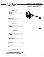
PNEUMATIC LEVEL CONTROLLER
MODEL: GEN 3
Installation, Operation & Maintenance Guide
MODEL: GEN 3
Installation, Operation & Maintenance Guide
www.kimray.com
4
CAUTION:
When ordered, the controller configuration & construction
materials were selected to meet specific pressure,
temperature, & fluid conditions. Do not subject the
controller to any other conditions without first contacting
the Kimray Inc, sales office or a sales / applications
representative.
A4 Tools Needed for Installation,
Conversions & Repair
This Kimray controller DOES NOT require special tools
for disassembly, inspection & assembly.
These are the standard tools required:
1. Pipe Wrench or other Wrench to fit 2-1/2" Flats.
2. 7/8" wrench for lower 1/2" NPTs
3. 9/16" wrench for Gauges -or- Adjustable Wrench
4. 9/16" socket for the mount screws
5. 3/8" Socket for Pilot Cartridge Caps
6. 1/4" hex key for 1/4" NPT plugs
7. 1/8" Hex Key (included with unit) see below.
8. Thread tape
9. Any equipment needed for tubing connections
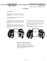
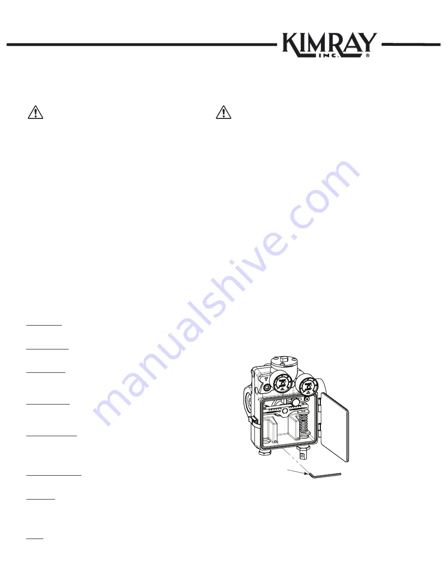
The Gen 3 includes a 1/8" hex key which will fit the pilot
& lever fasteners.
For convenience, the hex key can be stored in the
location shown below.
1/8" Hex key
CAUTION:
The instructions provided herein should be completely
reviewed & understood before installing, operating or
repairing this equipment. All
CAUTION
&
WARNING
notes must be strictly observed to prevent injury to
personnel or damage to equipment.
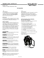
A1 Scope
This document contains information for the Gen 3 Liquid
Level Controller & includes detailed installation, operation
& repair/maintenance information for the product.
A2 Description
The Gen 3 Liquid Level Controller is designed for use in
single-phase & interface liquid control applications. The
pilot is capable of both Snap mode (on/off) & Throttle
mode (modulating). Pneumatic output can be set to
operate as Direct Acting or Indirect Acting. The mounting
body can be flipped to either Left Hand or Right Hand
Mount. The displacer may be assembled in vertical or
horizontal orientation. Changing between these options
does not require additional components nor swapping
out pilots.
A3 Definitions
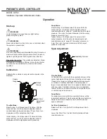
Snap Mode: On/Off, discrete output. Liquid level ranges
from high point to low point, large span.
Throttle Mode: Modulating, proportional output. Holds
consistent level, with very small span.
Direct Acting: For Fail Closed (FC) aka Pressure-to-Open
(PO) Valve. Pilot provides maximum output when liquid
level reaches set point at top of span.
Indirect Acting: For Fail Open (FO) aka Pressure-to-
Close (PC) Valve. Pilot provides maximum output when
liquid level reaches bottom of span.
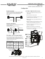
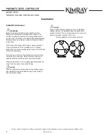
Left Hand Mount: With front of controller facing operator,
unit is mounted on left side of vessel. For Back Mount
applications, use this mount option due to the location of
the cover latch.
Right Hand Mount: With front of controller facing
operator, unit is mounted on right side of vessel.
Set Point: The liquid level at which the controller opens
the valve. In Snap Mode, this is at the top of the span. In
Throttle Mode, the liquid level should stay consistent at
the set point.
Span: Distance between the highest & lowest liquid level
during operation. This can be set with the Sensitivity
Fulcrum. See “Span Adjustment” below.
Introduction


