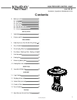
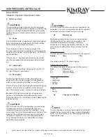
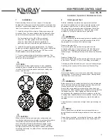
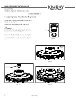
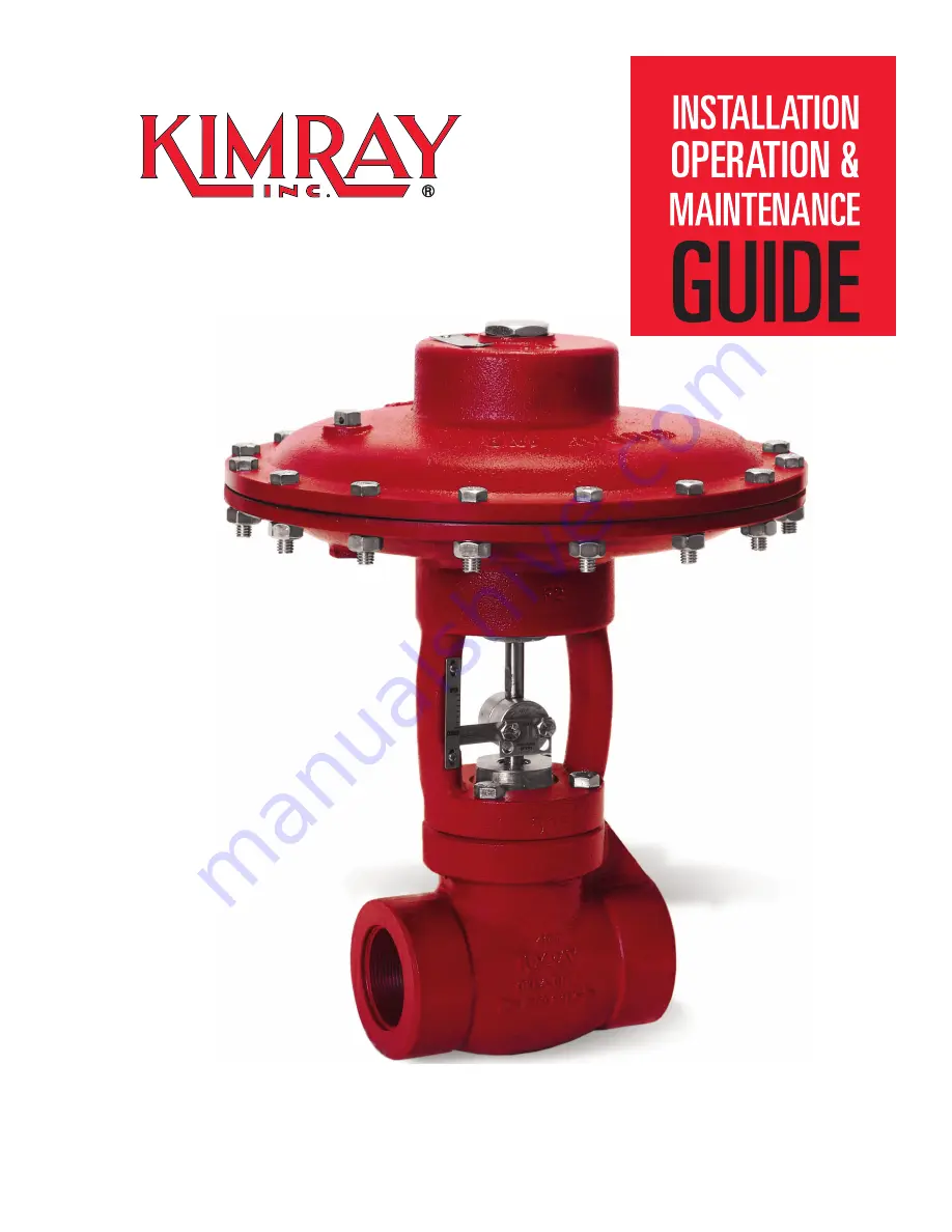
background image

HIGH PRESSURE CONTROL VALVE

STEM GUIDED

Summary of Contents for HPCV

Page 1: ...HIGH PRESSURE CONTROLVALVE STEM GUIDED...

Page 2: ...t to be construed as warranties for guarantees express or implied regarding Kimray products or services described herein or their use or application All sales are governed by our terms and conditions...

Page 3: ...ation 7 2 Start up and Test 7 DISASSEMBLY 3 Adjusting Screw Pivot Breather Plug Bonnet 8 4 Travel Indicator 9 5 Pivot Spring Plate Spring 9 6 Pivot Sleeve Diaphragm Plate Diaphragm Nut 10 7 Yoke Assem...

Page 4: ...install operate or maintain a control valve without being fully trained and qualified with the Kimray installa tion operation and maintenance manual To avoid personal injury or property damage it is i...

Page 5: ...odel PO PC SPECIAL TOOLS AND EQUIPMENT A6 Tip Kimray recommends using the above special tools and equipment for disassembly assembly and new part replacements Kimray Seat Cage Removal Tool Part No Lin...

Page 6: ...10 19 20 18 9 8 7 6 5 2 1 17 4 3 16 15 14 13 11 12 10 19 20 18 9 8 7 6 5 2 1 17 4 3 Item Part No Description Qty 1 Adjusting Screw 1 2 Pivot 1 3 Breather Plug 1 4 Bonnet 1 5 Spring Plate 2 6 Spring 1...

Page 7: ...ons representative 2 Start up and Test With the installation completed and appropriate relief and check valves installed and set slowly open the upstream and downstream shutoff valves In order to test...

Page 8: ...et See Fig 3 1 Remove Pivot from Adjusting Screw See Fig 3 2 NOTE Sometimes the Pivot will separate from the Adjusting Screw and sit on top of the Spring Plate Remove the Breather Plug from Bonnet See...

Page 9: ...the Pivot will separate from the Adjusting Screw and sit on top of the Spring Plate Remove Pivot from top of Spring Plate Remove Spring Plate Remove the spring from the Pivot sleeve See Fig 5 1 4 Trav...

Page 10: ...d spin the Diaphragm Plate in a counter clock wise direction loosening it from the Upper Stem See Fig 6 1 NOTE Peel the Diaphragm edge away from the Yoke rotate the Diaphragm Assembly off the Upper St...

Page 11: ...e a socket wrench to remove the Lower Adjusting Screw See Fig 7 2 Slide out the Upper Stem from the Lower Adjusting Screw See Fig 7 3 Remove O Ring from the inside of the Lower Adjusting Screw Use a p...

Page 12: ...N When removing Packing Box from Body if pressure starts to exit out of the safety relief hole than stop and check on isolation NOTE Occasionally the Cage unscrews from the Packing Box leaving the Cag...

Page 13: ...t with an adjustable wrench Leave the Seat attached to Cage Insert a screw driver or small bar through the Cage and unscrew See Fig 9 1 NOTE Leaving the Seat attached will prevent the Cage from damagi...

Page 14: ...hrough the bottom of the Packing Box Check all parts for damages NOTE Apply all purpose grease the inside of the Packing Box before inserting parts Insert new Felt Wiper Item 3 Insert new Felt Retaine...

Page 15: ...e to heavy damage See Fig 11 3 Fig 11 4 Ball and Stem Inspect the ball for pits and or grooves and inspect the Stem for extensive scoring or scratches Check for any bends on the Stem See Fig 11 1 Insp...

Page 16: ...ard to seal such as parallel threads or threads on fittings subject to vibration more than three wraps may be necessary Insert Packing Box into the Body Use an adjustable wrench on flats for tightenin...

Page 17: ...lean it to one side and turn ring while pressing it onto stem See Fig 12 5 5 Install the second black V C ring followed by the white V ring D in the same way you installed the first black ring 6 Slide...

Page 18: ...e sure the Diaphragm does not wrinkle Insert Diaphragm Assembly in the center of the Yoke See Fig 13 2 Place the Yoke on top of Body Insert Bolts and tighten with a wrench Use an adjustable wrench to...

Page 19: ...the Spring on the Sleeve Insert the second Spring Plate on top of the Stem Place Bonnet on top of internal assembly and insert screws See Fig 14 3 NOTE Make sure you tighten the Bolts in a criss cross...

Page 20: ...ert Bolts in Bonnet and tighten See Fig 15 2 Insert O Ring not shown on the Upper Adjusting Screw and tighten it on top of Bonnet See Fig 15 3 Insert Breather Plug See Fig 15 4 NOTE Make sure you tigh...

Page 21: ...TE Make sure the Travel Indicator Tag shows the correct operation of the valve either PO or PC Insert Breather Plug When assembling the Coupling Block make sure the bevels are in the same side of the...

Page 22: ...ck for any leakage Check Travel Indicator See Fig 17 2 Install the Nameplate on top of the Bonnet with two drive screws and a ball peen hammer Replace the male nipple with a blue plug and thread it in...

Page 23: ...001 certified manufacturer Kimray quality assurance process maintains strict controls of materials and the certification of parts used in Kimray HPCV Please visit our website for up to date product da...

Page 24: ...2015 Kimray Inc 1 15 MKSLLS RM0002 Issued 4 21 Kimray com...

Reviews: