Float Operated Level Controllers
Models Pneumatic GEN II
Installation and Maintenance
1
IM0015
Kimray Inc.- 52 NW 42nd Street Oklahoma City, Ok 73118 USA - Ph: (405) 525-6601, Fax: (405) 525-7520 - Kimray.com
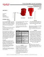
INTRODUCTION
CAUTION
Prior to installing, the instructions provided
herein should be completely reviewed and
understood before operating or repairing this
equipment . All CAUTION and WARNING
notes must be strictly observed to prevent
personal injury or equipment damage.
Scope
This installation manual includes instructions
and maintenance information for both
Kimray pnuematic side mount and back
mount level controllers.
Do not install, operate, or maintain a
pneumatic GEN II without being fully trained
and qualified with Kimray installation and
maintenance manual. To avoid personal
injury or property damage, it is important to
carefully read, understand, and follow all the
contents of this manual, including all safety
cautions and warnings. If you have any
questions about these instructions, contact
your Kimray applications support group
before proceeding.
CONTENTS
PAGE
Introduction
1
Scope
1
Description
1
Specification
1
Control Installation
2
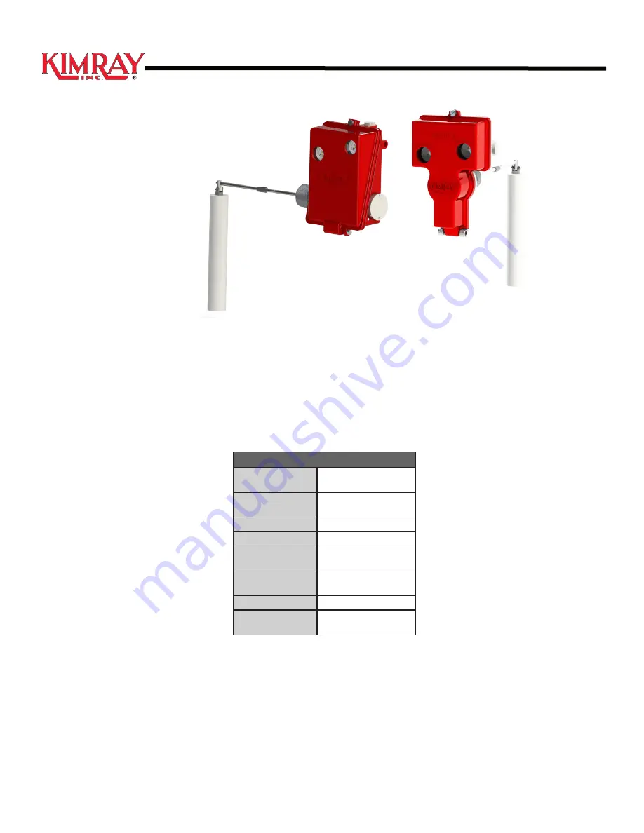
Table 1 -
General Specifications
Description:
Pneumatically Operated
Level Controller.
Operating
Pressure:
(0-4000) psig (276 Bar)
Connection Size:
2in. - 6in.
Body Material:
Steel
Connection Type:
NPT, Flg, Grv, HU
Grooved
Actuation:
Snap, Throttle
Adjustable
Control Range:
2 - 10 in.
Temperature:
-50° to 300° F
-45° to 149° C
Specification
Description
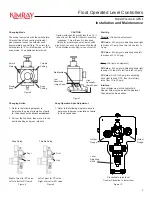
The GEN II side mount and back mount
level controllers are designed for use in
liquid
level and liquid/liquid interface control
applications
. Both provide either a
throttle
modulating or snap on/off pneumatic
output and can be set to operate in a
direct increasing liquid level output signal
or
indirect mode increasing liquid level
decreasing output signal
.
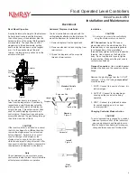
The GEN II level controllers are equipped
with a displacer or hanger for horizontal or
vertical installation.
Before beginning installation of the GEN II
•Read and follow instructions.
•Make sure all pressure has been removed
from the vessel before opening any connec
tions.
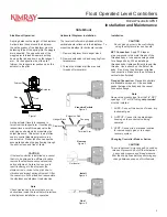
WARNING
If a level controller is used in a hazardous
or flammable fluid service, personal injury
and property damage could occur due to
fire or explosion of vented fluid that may
have accumulated. To prevent such injury
or damage, install piping or tubing to vent
the fluid to a safe, well-ventilated area
or containment vessel. When venting a
hazardous fluid, the piping or tubing should
be located far enough away from any
buildings or windows so as not to create
further hazard. The vent opening should
be protected against anything which could
obstruct it, or it should by connected to
exhaust tubing or tubing connected to a
vapor recovery system.
Vent
Periodically check the vent opening or
the end of the remote vent pipe, if one is
required. Be certain they are clear. If a vent
should become blocked the pilot could lose
control.
CAUTION
When ordered, the GEN II level controller
configuration and construction materials
were selected to meet specific pressure,
temperature, pressure drop and fluid
conditions. Since some body/trim material
combinations are limited in their pressure
drop and temperature ranges, do not subject
the GEN II level controller to any other
conditions without first contacting the Kimray
Inc, sales office or a sales / applications
representative.
WARNING
Do not exceed the maximum pressure
specified on the controller nameplate. Under
no circumstances should the controller
supply pressure ever exceed the maximum
psig.
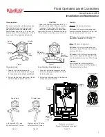
The side mounted is reversible for rigtht hand
or left hand installation. The
back mount is center back mounted. Both
models are standard with a 1/4” NPT tapped
vent. No gas is released into the case.
Both models include a 40 micron filter
located just downstream of the instrument
gas inlet port.
Back Mount
Side Mount
Issued 6/19


