19
Chapter 4 Digital Operation Panel
4.1 Introduction
A digital operation panel functions to set user parameters in a servo driver, execute instructions, or display
parameters. Table 4-1 describes all display contents and functions of the digital operation panel.
Table 4-1 Display contents and functions of a digital operation panel
Number/
Point/Key
Function
①
Indicates whether data is positive or negative. If it is on, it indicates negative; otherwise it indicates
positive.
②
1. Distinguishes the current object group and the address data in this object group during
parameter settings.
2. Indicates the higher 16 bits of the current 32-bit data when internal 32-bit data is displayed in
15
/W
signals of encoder
Summary of Contents for CD2S Series
Page 7: ...7...
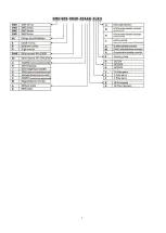
Page 8: ...8 1 3 3 Power Brake and Encoder cable of Motors...
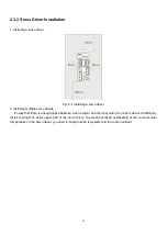
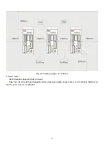
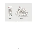
Page 12: ...12 Fig 2 3 Installation direction...
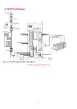
Page 15: ...15 3 1 2 Wiring Diagram Fig 3 1 Wiring diagram of CD2S driver...
Page 23: ...23 Fig 4 3 Separate regulation of bits...
Page 82: ...82...
Page 96: ...96 8 4 Debugging example 8 4 1 Oscilloscope 1 Enter oscilloscope 2 Parameters for Oscilloscope...
Page 98: ...98 In Auto Reverse mode Kvp 110...
Page 100: ...100 The oscilloscope is as following max following error is 69 inc Fig 2 Kpp 30 Vff 100...
Page 101: ...101 The oscilloscope is as following max following error is 53 inc Fig 3 Kpp 30 Vff 50...
Page 102: ...102 The oscilloscope is as following max following error is 230 inc...

