69
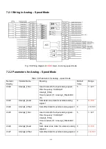
d3.23
Analog1_Dead
Sets dead zone data for external analog
signal 1
0
0~10V
d3.24
Analog1_Offse
t
Sets offset data for external analog
signal 1
0
-10~1
0V
d3.25
Analog2_Filter
Used to smooth the input analog
signals.
Filter frequency: f=4000/(2π*
Analog1_Filter)
Time Constant (T) =
Analog2_Filter/4000 (S)
5
1~127
d3.26
Analog2_Dead
Sets dead zone data for external analog
signal 2
0
0~10V
d3.27
Analog2_Offse
t
Sets offset data for external analog
signal 2
0
-10~1
0V
d3.30
Analog_Torqu
e_Con
Selects analog - torque channels
0: Invalid analog channel
1: Valid analog channel 1 (AIN1)
2: Valid analog channel 2 (AIN2)
Valid mode 4
0
0~2
d3.31
Analog_Torque
_Factor
Sets the proportion between analog
signals and output torque (current)
0
/
d2.15
Speed_Limit_F
actor
The factor that limits the maximum
speed in the torque mode
V
max_speed
complies with d2.24
Max_Speed_RPM parameter settings.
0
/
d2.24
Max_Speed_R
PM
Limits the max rotation speed of the
motor
5000
0~100
00rpm
7.3.3 Analog Signal Processing
In the analog
– torque mode, external analog command signals are directly inputted to the current loops
in the driver, thus directly controlling target current through the internal current loop. Analog signal is
processed in the same way as that in the analog
– speed mode.
Table 7-17
t
K
and
Ipeak
parameters
Motor Model
t
K
(Nm/A)
Driver Model
Ipeak
(A)
SMH40S-0050-30AXK-4LKH
0.265
CD412S-AA-000
12
Summary of Contents for CD2S Series
Page 7: ...7...
Page 8: ...8 1 3 3 Power Brake and Encoder cable of Motors...
Page 12: ...12 Fig 2 3 Installation direction...
Page 15: ...15 3 1 2 Wiring Diagram Fig 3 1 Wiring diagram of CD2S driver...
Page 23: ...23 Fig 4 3 Separate regulation of bits...
Page 82: ...82...
Page 96: ...96 8 4 Debugging example 8 4 1 Oscilloscope 1 Enter oscilloscope 2 Parameters for Oscilloscope...
Page 98: ...98 In Auto Reverse mode Kvp 110...
Page 100: ...100 The oscilloscope is as following max following error is 69 inc Fig 2 Kpp 30 Vff 100...
Page 101: ...101 The oscilloscope is as following max following error is 53 inc Fig 3 Kpp 30 Vff 50...
Page 102: ...102 The oscilloscope is as following max following error is 230 inc...


