55
setting frequency and operating time of the steps.There
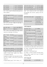
parameters are defined in group C2.
PLC step finish signal and PLC cycle finish signal can
be defined in open collector output Y1,
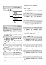
C2.00 Simple PLC operation
mode selector
0~1123H
【
0000
】
The unit’s place of LED:PLC function running mode
0:No function.
Simple PLC function is invalid.
1:Stop after single cycle.
As shown in Fig.6-47,the drive will stop automatically
after finishing one cycle running,the wait for another
start signal to startup.
Fig.6-47 Stop after single cycle
2.Keep final states after single cycle
As shown in Fig.6-48,the drive will keep running at the
frequency and direction in last step after finishing single
cycle.
Fig.6-48 Keep final states after single cycle
3.Continuous cycle
As shown in Fig.6-49,the drive will continue next cycle
after finishing one cycle,and stop when there is stop
command.
Fig.6-49 Continuous cycle
The ten’s place of LED:Start modes
0:Start from first step
If the drive stop while it was running(Caused by stop
command,fault or power failure), then it will start from
first step when it restart.
1:Start from the step before stop(or alarm)
If the drive stop while it was running(Caused by stop
command or fault), then it will record the operating time
of current step,and start from this step and continue the
left operating time when it restart,as shown in Fig.6-50.
A
B
C
D
0:
No function
1:
Stop after single cycle
2:
Keep final states after single cycle
3:
Continuous cycle
0:
Start from first step
1:
Start from the step before stop
(or alarm).
2:
before stop(or alarm)
Start from the step and frequency
Storage after power off
0:
Disable
1:
Save the segment,frequency when
power off
Time unit selector for each step
0:
Second
1:
Minute
Start mode


