Issue
N
C.S.
04.03.20
Trading Estate Farnham Surrey England
Doc. No. TD 120
Page 5 of 25
Title : Installation, Operation & Maintenance Instructions – IS Digital EL Positioner
3.3.3 Positioner Signal.
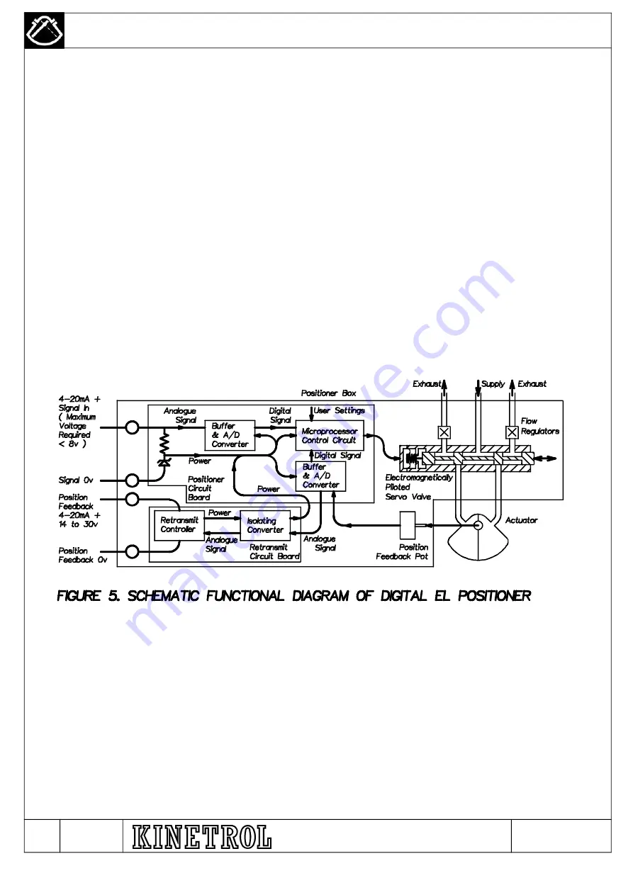
The positioner signal must be 4-20mA. The positioner gives a positioning response between 0 and 90 degrees linearly or non-
linearly related to the signal. The positioner is loop powered – that is the signal itself supplies all the electrical power, and no
separate power source is needed. In order to supply enough power, the unit needs between approximately 6 and 8 volts to
drive the signal current through it – it behaves electrically like a resistor in series with a zener diode. A typical 4-20mA source
with a 24v DC supply is compatible with this input, and can drive a full signal through both a 28v 300 ohm barrier and the
positioner with parameters given on page 16.
3.3.4 Angle Retransmit Supply.
The optional angle retransmit circuit is also loop powered, requiring 14 to 24 volts DC to drive the 4-20mA current through it –
the current passed is linearly proportional to the actual positioner shaft angle. Like the signal supply, it must also be powered
through a separate 28v 300ohm barrier with parameters shown on page 16. The retransmit circuit reads the same angle
transducing potentiometer as the positioner circuit – however, the angle retransmit circuit remains functional on loss of
positioning signal and/or air supply, and conversely the positioner remains functional, as long as a signal is present, even if the
angle retransmit circuit is fitted and there is no supply to energise its loop. Nevertheless, the angle retransmit circuit is
electrically isolated from the positioner signal circuit.
3.3.5 Feedback Switches
There are two types of feedback switches that can be fitted, these are:
(a) Two V3 type micro switches with independent adjustable operating strikers. Each switch must be connected to its own
barrier – suggested 28v 300 ohm barrier with parameter's shown on page 16.
(b) Two V3 type proximity sensors. These are powered from a nominal 8v source and must be connected independently to a
barrier having the following maximum parameter's: Ui = 16v, Ii = 25mA, Pi = 64mW as shown on page 16.
4. SCHEMATIC FUNCTIONAL DIAGRAM.
N – AR7059 / M – AR6971 / L - AR6419 / K - AR6347 / J-AR6096 / H – AR 6082 / G – AR 5487 / F – AR 5608 / E - AR 5293


