Issue
N
C.S.
04.03.20
Trading Estate Farnham Surrey England
Doc. No. TD 120
Page 6 of 25
Title : Installation, Operation & Maintenance Instructions – IS Digital EL Positioner
5. SET UP.
5.0 Introduction
When the positioner/actuator combination is installed in its application, set up the control adjustments if necessary. For most
applications, it is likely that the factory settings will be satisfactory – the low and high current points are set to give 0-90 degree
movement in response to a 4-20mA signal, the flow regulators are set for maximum travel speed, and the proportional gain and
damping settings adjusted for a good level of sensitivity and smoothness suitable for most applications. The jumper is set in the
“off” position to give a linear characteristic with travel extrapolated beyond the low and high current settings. If you need to
change the settings, read the following section carefully.
5.1 Setting Travel Speed.
Set the travel speed using the exhaust flow adjuster screws (see Figure 4.).
This only applies if you want to reduce the speed from its supplied maximum
factory setting.
5.2 Setting Limit Switch Cams (Optional Equipment).
Limit switch cams are factory set (if fitted) to give end-of-travel switching with
one switch at each end. The two possible types of coupling require slightly
different approaches to setting.
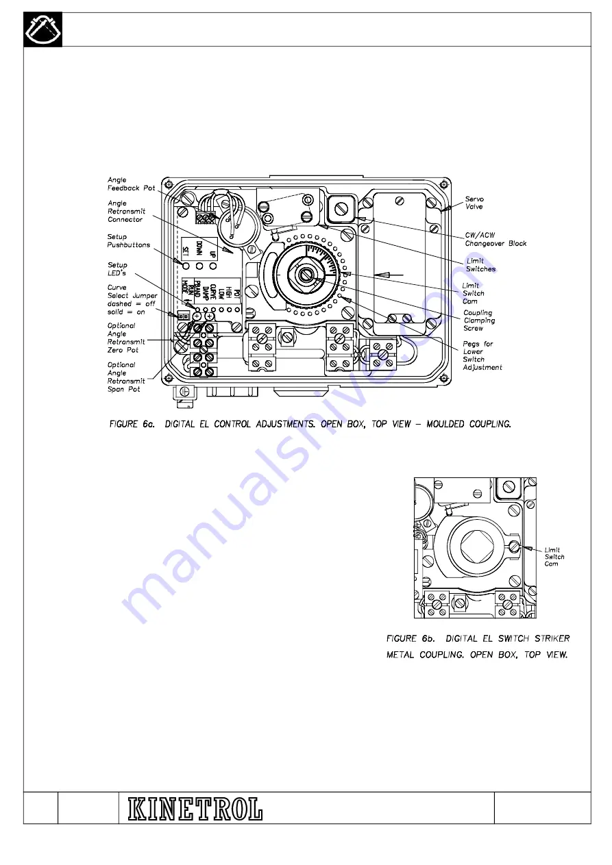
5.2.1
Moulded coupling cams, shown in figure 6a, can be adjusted using light
pressure to rotate in 1 degree increments. Adjust the lower cam first using a
screwdriver to lever against special pegs moulded into the carrier plate or
use finger pressure. Secondly move the upper cam using finger pressure
only. Graduated marks on the top of the coupling are provided to gauge the
position of the actuator with the lid removed. This can be lined up with an
arrow marked on the servo valve lid.
5.2.2
Metal coupling cams are adjusted by releasing the screw shown in figure 6b, moving to desired position and re
tightening. Set the lever cam first. Ensure the clamp section of the cam does not strike a switch at any part in the actuator's
travel.
N – AR7059 / M – AR6971 / L - AR6419 / K - AR6347 / J-AR6096 / H – AR 6082 / G – AR 5487 / F – AR 5608 / E - AR 5293


