background image

30

The 

KINEX-Ankle

device is subject to

particular precautions regarding electro-
magnetic compatibility (EMC). The de-
vice must be installed and put into
service strictly in compliance with the
EMC directives put forth in the accom-
panying documents.

Portable and mobile RF communication
systems may affect the 

KINEX-Ankle

device.

The 

KINEX-Ankle

device should not be

used adjacent to or stacked with other
equipment. If adjacent or stacked use is
necessary, 

KINEX-Ankle

should be ob-

served to verify normal operation in the
configuration in which 
it will be used.

If you detect damage or malfunctions
that may impair the safety of the patient
or of the operator, have the device 
repaired before using it.

If it is necessary to replace assemblies or
cables, only the manufacturer's original
parts must be used to ensure continued
compliance with EMC requirements
after repair. This requirement applies to
the power supply unit, cables and cable
lengths, drive unit consisting of the
motor and the control system, the pro-
gramming unit incl. the coiled cable and
the connector.

Electromagnetic environment –

guidance

KINEX-Ankle

uses RF energy only for its

internal function. Therefore, its RF emissi-
ons are very low and are not likely to cause
any interference in nearby electronic equip-
ment.

KINEX-Ankle

is suitable for use in all

establishments, including domestic and
those directly connected to the public low-
voltage power supply network that supplies
buildings used for domestic purposes.

Guidance and Manufacturer’s Declaration – Electromagnetic Emissions

KINEX-Ankle

is intended for use in the electromagnetic environment 

specified below. It is the responsibility of the customer or user to ensure that the 

KINEX-Ankle

device is used in such an environment.

Emissions test

RF emissions to
CISPR 11

RF emissions to
CISPR 11

Harmonic emissions to
IEC 61000-3-2

Voltage fluctuations/flik-
ker emissions to IEC
61000-3-3

9.1 Electromagnetic emissions

Compliance

Group 1

Class B

not applicable

not applicable

9. IEC 60601-1-2:2001

KINEX-Ankle Gebr DV2 706  16.07.2007  14:03 Uhr  Seite 30

Summary of Contents for KA2 Ankle CPM

Page 1: ...1 1801 Airport Road Suite D Waukesha WI 53188 Phone 800 845 6364 Fax 888 845 3342 KINEX KA2 ANKLE Ankle CPM Machine...

Page 2: ...2 3 1 23 22 21 20 15 14 10 12 13 11 19 17 18 16 1 7 4 5 8 9 6 Device description 2...

Page 3: ...A C E B D F G H KINEX Ankle setup illustrations 3...

Page 4: ...setup 15 4 1 Connecting the device performance check 15 4 2 Adjusting the device to the patient 16 5 Setting the treatment values 17 5 1 General information on programming KINEX Ankle 17 5 2 Programmi...

Page 5: ...stic paralysis unstable osteosynthesis 1 3 Indications 1 4 Contraindications KINEX Ankle is a motor operated Con tinuous Passive Motion CPM device providing motion to the ankle joint Suitable for use...

Page 6: ...t the height of the carriage 20 Perforation to set the height of the carriage 21 Programming unit 22 Nameplate 23 Connection for programming unit 2 1 Description of the device components The motorized...

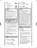
Page 7: ...et dorsal extension value set plantar flexion value motor A selected direction of motion set angle of motor B current position of motor B left or right solid foot symbol arrow pointing inward inversio...

Page 8: ...own plantar flexion selected MENU level selected function current maximum dorsal extension value current maximum plantar flexion value set carriage angle selected parameter here dorsal extension set c...

Page 9: ...selected function status of the selected function here speed 9 2 2 4 Programming unit in general programming mode...

Page 10: ...oad reversal motor B motor A ON OFF motor B ON OFF transport setting synchronized non synchronized mode total therapy time service menu warm up protocol isolation protocol dorsal extension plantar fle...

Page 11: ...connections and nameplate alternating current protective earth connection type B applied part power switch OFF power switch ON Refer to accompanying documents Do not dispose of product with unsorted...

Page 12: ...uals are allowed to operate the KINEX Ankle de vice Individuals are authorized after receiving training in the operation of the device and reading this opera tion manual Before using the device the op...

Page 13: ...e allow the KINEX Ankle to reach room temperature If the device has been transported at temperatures below 0 C 32 F leave it to dry at room temperature for about 2 hours until any conden sation has di...

Page 14: ...g parts during operation Inspect KINEX Ankle for damage and loose connections at least once a year Damaged and worn parts must immediately be replaced with original spare parts by author ized staff Ca...

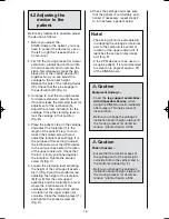
Page 15: ...acket for dorsal extension plantar flexion 15 until it forms an angle of 45 with the base Close the clamping lever to lock the carriage in that position Fig B 4 1 Connecting the device performance che...

Page 16: ...ever adjusting the height of the calf support assem bly 1 Fig D and the knurled screw adjusting the height of the footplate 8 Fig E Set the calf support assembly and the footplate to a level where the...

Page 17: ...lue is displayed The symbol above the parameter key appears in reverse video 4 With the keys plus minus you change the displayed value When you press and hold the key the value will change at a higher...

Page 18: ...stop function KINEX Ankle will stop immediately when any of the keys is pressed during therapy When the START key is pressed in the synchronized mode the carriage will move to the position halfway bet...

Page 19: ...ses Pauses occur at each programmed maximum value These are the three pause points maximum dorsal value at the same time as halfway between inversion eversion maximum eversion value at the same time a...

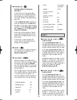
Page 20: ...dorsal extension 20 plantar flexion 20 inversion 5 eversion 15 pauses 0 timer continuous operation speed 50 reverse on load motor A 25 reverse on load motor B 25 motor A ON motor B ON synchronized mod...

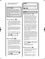
Page 21: ...manufacturer can not be held liable for misuse of this feature warm up protocol During warm up the patient will slowly become used to the set maxi mum dorsal extension plantar flex ion and inversion e...

Page 22: ...the key plus Deactivate the func tion by pressing the key minus In this case it is not possible to acti vate deactive the function by press ing the parameter key again A check mark appears in the circ...

Page 23: ...opposite direction This stretch cycle is repeated ten times After that the carriage moves to the programmed maximum plantar flexion value and restarts the dorsal exten LEVEL 5 sion stretch cycle defa...

Page 24: ...maximum inversion value and restarts the eversion stretch cycle default setting disabled stretching in inversion With the special stretching in inver sion function the carriage gently stretches the jo...

Page 25: ...aximum dorsal ex tension value and to the value halfway between inversion and eversion After reaching this position the cycle restarts maximum eversion at the same time as halfway between dorsal exten...

Page 26: ...cal damage before each use If you detect damage or malfunctions that may impair the safety of the patient or of the operator have the device re paired before using it For safety the devices require re...

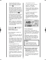
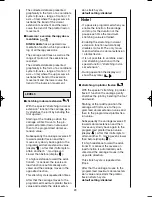
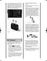
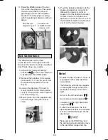
Page 27: ...it 6 Relieve the strain on the carriage by lifting it a little at the moving bracket for dorsal extension plantar flexion 15 and open the clamping lever which adjusts the inclination of the carriage 5...

Page 28: ...d the carriage will automatically move to the permitted range and stop 11 Place the KINEX Ankle at the bot tom of the shipping box Then pack the two extra boxes for the pro gramming unit and the footp...

Page 29: ...15 5 In Weight 11 kg 27 2 lb Materials used ABS POM Delrin 100 PUR PA FR4 aluminum stainless steel brass MDD class 2a Standards compliance IEC 60601 1 1988 A1 1991 A2 1995 Certification ANSI UL 60601...

Page 30: ...supply unit cables and cable lengths drive unit consisting of the motor and the control system the pro gramming unit incl the coiled cable and the connector Electromagnetic environment guidance KINEX...

Page 31: ...Declaration Electromagnetic Immunity KINEX Ankle is intended for use in the electromagnetic environment specified below It is the responsibility of the customer or user to ensure that the KINEX Ankle...

Page 32: ...requency rangeb Interference may occur in the vicinity of equipment marked with the following symbol NOTE 1 At 80 MHz and 800 MHz the higher frequency range applies NOTE 2 These guidelines may not app...

Page 33: ...on is affected by absorption and reflection from structures objects and people 9 3 Recommended separation distances between portable and mobile RF communications equipment and the KINEX Ankle device s...

Page 34: ...it to the transport position see chapter 6 3 Refer to the Service Manual for the most recent list of spare parts When ordering spare parts always specify item description part number quantity serial...

Page 35: ...lation protocol dorsal extension inversion eversion plantar flexion therapy documentation therapy documentation stretching in stretching in stretching in inversion stretching in eversion dorsalextensi...

Page 36: ...1801 Airport Road Suite D Waukesha WI 53188 Phone 800 845 6364 Fax 888 845 3342 www kinexmedical com ML 1402...

Reviews: