ASSEMBLY & OPERATION
Warning!
For your own safety, do not connect the log splitter to the power
source until the machine is completely assembled and you have read and
understood the entire instruction manual.
Warning!
Never use the log splitter if it is not in perfect order or if it needs
servicing. Before starting work, check correct functioning of all the safety
devices (power button).
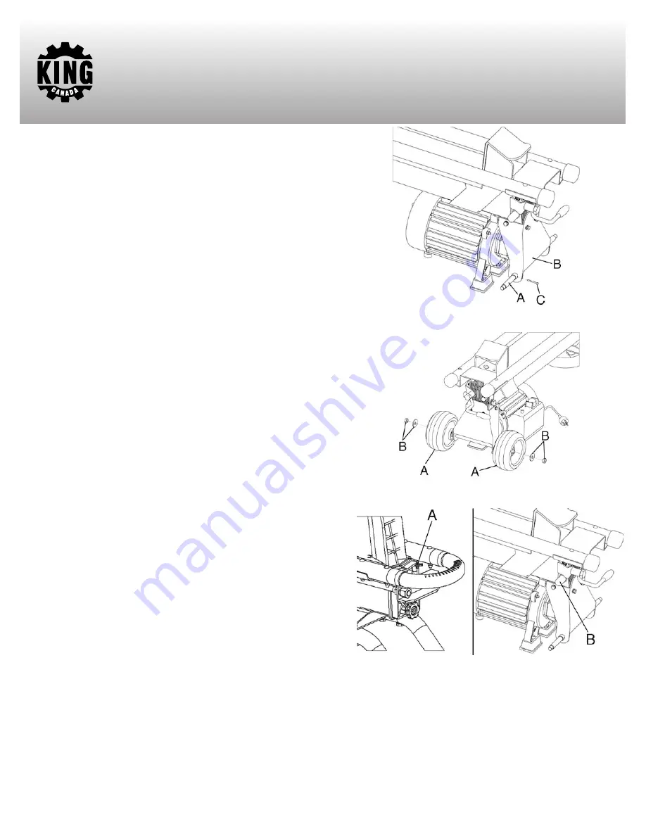
Assembling Wheels
Before operating the log splitter, it is necessary to fit both wheels on the
supporting shaft.
1) Slide the wheel shaft (A) Fig.4 into the wheel bracket (B). Secure the
wheel shaft with the provided cotter pins (C).
2) Slide both wheels (A) Fig.5 onto the wheel shaft and secure them using
the washers and lock nuts (B).
Operation
VERY IMPORTANT
WARNING! BEFORE OPERATING THE LOG SPLITTER, THE BLEED
SCREW (A) FIG.6 MUST BE LOOSENED BY SOME ROTATIONS UNTIL
AIR CAN GO IN AND OUT OF THE OIL TANK SMOOTHLY.
AIR FLOW THROUGH THE BLEED SCREW HOLE SHOULD BE
DETECTABLE WHILE THE LOG SPLITTER IS UNDER OPERATION.
BEFORE MOVING THE LOG SPLITTER, MAKE SURE THE BLEED
SCREW IS TIGHTENED TO AVOID OIL LEAKING FROM THIS POINT.
FAILURE TO LOOSEN THE BLEED SCREW WILL KEEP THE SEALED
AIR IN HYDRAULIC SYSTEM BEING COMPRESSED AFTER BEING
DECOMPRESSED. SUCH CONTINUOUS AIR COMPRESSION AND
DECOMPRESSION WILL BLOW OUT THE SEALS OF THE HYDRAULIC
SYSTEM AND CAUSE PERMANENT DAMAGE TO THE LOG
SPLITTER. DO NOT ADJUST THE MAX PRESSURE LIMITING SCREW
(B) Fig.6.
Max pressure was set during production and the max pressure limiting
screw is tightened to ensure the log splitter works under pressure of no
more than 6 tons. The setting was done by qualified mechanics with
professional instruments. Unauthorized resetting will cause the hydraulic
pump to fail to output enough splitting pressure or RESULT IN SERIOUS
INJURY AS WELL AS DAMAGE TO THE MACHINE. The max pressure
limiting screw (B) Fig.6 is protected by a plastic cap. If the plastic cap gets
loosened, adjust it.
FIGURE 4
FIGURE 5
FIGURE 6


