ADJUSTMENTS
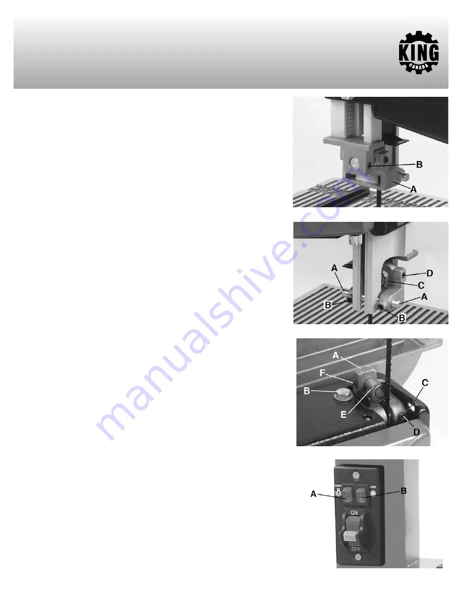
FIGURE 12
WARNING!
Turn off the saw, remove the main On/Off switch safety key and unplug the
power cord before making any adjustments on the saw.
ADJUSTING UPPER AND LOWER BLADE GUIDES AND BACK-UP BEARINGS
NOTE: The upper and lower blade guides and back-up bearings support the
bandsaw blade during cutting operations. The adjustment of the guides and
bearings should be checked whenever a different blade is installed.
NOTE: Allowing the blade teeth to hit the blade guides while the saw is in use will
ruin the blade and may damage the sharpened edge of the teeth. Proper
adjustment of the upper and lower blade guide assemblies will help prevent this
from occurring.
1) Adjust the position of the upper blade guide support (A) Fig.12 first. Loosen set screw
(B) using a hex. key.
2) Slide the blade guide support until the front edge of the blade guides (A) Fig.13 are
about 1/32” behind the gullet of the blade (behind the blade teeth). Tighten the set
screw.
3) Repeat for the lower blade guide support. Adjust the position of the lower blade guide
support (A) Fig.14. Loosen hex. nut and bolt (B).
4) Slide the blade guide support until the front edge of the blade guides (C) Fig.14 are
about 1/32” behind the gullet of the blade (behind the blade teeth). Tighten the hex. nut
and bolt.
5) Adjust the upper blade guide pins (A) Fig.13. Loosen the two set screws (B) and press
the two guide pins evenly against the sides of the blade. Make sure that you don’t pinch
the blade. Release the guide pins and rotate the upper wheel, moving the blade
downward. Make sure that one guide pin is not further away from the blade than the
other. Tighten both set screws (B).
6) Repeat on the lower blade guide pins (C) Fig.14 using set screws (D).
7) Adjust the upper back-up bearing. Loosen the upper bearing set screw (D) Fig.13 using
a hex. key.
8) Move the back-up bearing within 1/32” of the blade. Tighten the upper bearing set screw.
9) Repeat on the lower back-up bearing (E) Fig.14 using set screw (F).
NOTE: The back-up bearing is intended to support the back edge of the blade while
cutting. The blade should not contact the bearings when cutting is stopped.
TURNING WORK LIGHT AND LASER GUIDE ON/OFF
1) To turn the work light On, press the work light switch (A) Fig.15 upwards to the “I” On
position. To turn the work light Off, press the work light switch downwards to the “O” Off
position.
2) To turn the laser guide On, press the laser guide switch (B) Fig.15 upwards to the “I”
On position. To turn the laser guide Off, press the laser guide switch downwards to the
“O” Off position. Go to next page for laser guide adjustment.
FIGURE 13
FIGURE 14
FIGURE 15


