background image

INSTALLATION

INSTALLATION

INSTALLING  PVC  SLEEVE  CONNECTOR  TO

GENERATOR POWER INLET bOX 

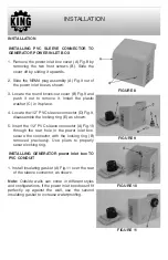
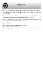
1. Remove the power inlet box cover (A) Fig.8 by

removing  the  two  front  screws  (B).  Slide  the

cover off by sliding it upwards.

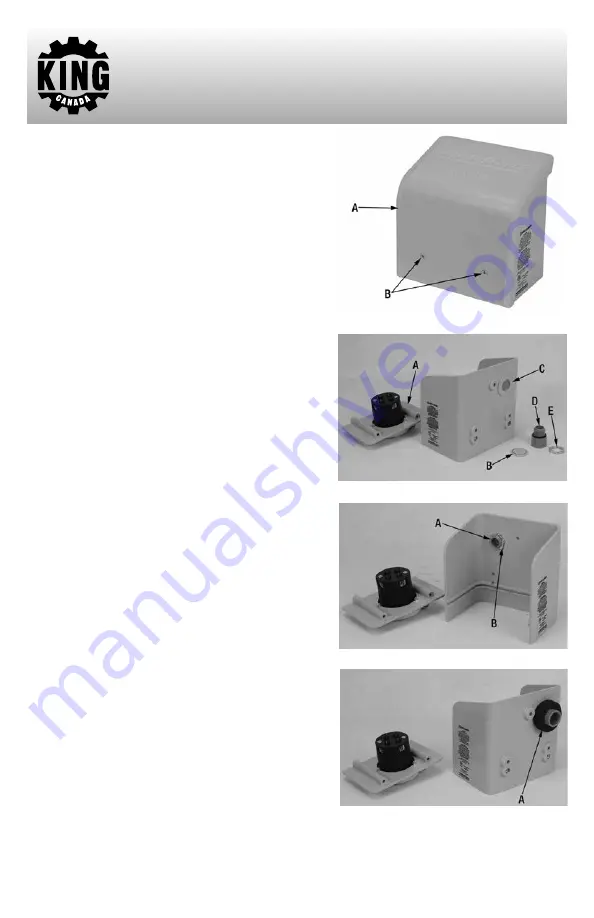
2. Slide the NEMA plug assembly (A) Fig.9 out of

the power inlet box as shown.

3. Locate the round knock-out cover (B) Fig.9 and

push  it  out  to  remove  it.  Install  the  plastic

washer (C) in its place.

4. Locate the 1/2” PVC sleeve connector (D) Fig.9,

disassemble the locking ring (E) as shown.

5. Insert the 1/2” PVC sleeve connector (A) Fig.10

through  the  rear  hole  in  the  power  inlet  box,

secure  the  connector  with  the  locking  ring  (B)

removed  previously.  Use  pliers  to  properly

secure locking ring.

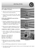
INSTALLING GENERATOR power inlet box TO

PVC CONDUIT

1. Install insulating gasket (A) Fig.11 over the rear

of the sleeve connector, as shown. 

Note:

Outside  walls  can  come  in  different  styles

and configurations, if the power inlet box doesn’t fit

perfectly  up  against  the  wall,  use  the  second

insulating gasket to increase waterproofing.

FIGURE 8

FIGURE 9

FIGURE 10

FIGURE 11

Summary of Contents for POWER FORCE K-X7500

Page 1: ...INSTRUCTION MANUAL COPYRIGHT 2019 ALL RIGHTS RESERVED BY KING CANADA TOOLS INC MODEL K X7500 GENERATOR HOME CONNECTION KIT...

Page 2: ...d lack of maintenance King Canada shall in no event be liable for death injuries to persons or property or for incidental special or consequential damages arising from the use of our products To take...

Page 3: ...r 4 Mount outdoor power inlet box 24 above grade 24 from the ground 5 USE COPPER WIRE ONLY 6 Use 1 2 or 3 4 conduit only 7 Only plug one appliance per receptacle Never use an extension cord or multi p...

Page 4: ...that a portable generator and a 30 Amp 125 250VAC L14 30 generator cord are not included and must be purchased INSTALLATION CONSIDERATIONS LOCATION BEFORE INSTALLATION We recommended that you check if...

Page 5: ...of the wall for any electrical wiring water pipes etc If everything looks clear continue drilling at full speed 3 Once the spade bit reaches the wall insulation reduce forward pressure to make sure t...

Page 6: ...outlet power panel assembly Pull wires out of the conduit then cut the conduit on your pencil mark Once cut reassemble the conduit to the cradle at the rear of the outlet power panel and reinsert ass...

Page 7: ...connector D Fig 9 disassemble the locking ring E as shown 5 Insert the 1 2 PVC sleeve connector A Fig 10 through the rear hole in the power inlet box secure the connector with the locking ring B remo...

Page 8: ...ten so much that it distorts the box 2 Make sure the insulation gasket s A Fig 11 is compressed enough to ensure waterproofing CONNECTING WIRES TO NEMA L14 30 PLUG 1 While holding the NEMA plug assemb...

Page 9: ...plug underneath the power inlet box installed on the outside of your home 3 Start the generator Now the LED lights of the outlet power panel inside your home should be on indicating that the panel is...

Reviews: