INSTALLATION
INSTALLING GENERATOR power inlet box TO
PVC CONDUIT continued...
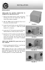
2. Insert the 4 wires from the outlet power panel
through the PVC sleeve connector.
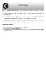
3. Insert the PVC conduit into the PVC sleeve
connector at the back of the power inlet box.
See Fig.12.
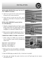
INSTALLING GENERATOR power inlet box
TO OUTSIDE WALL
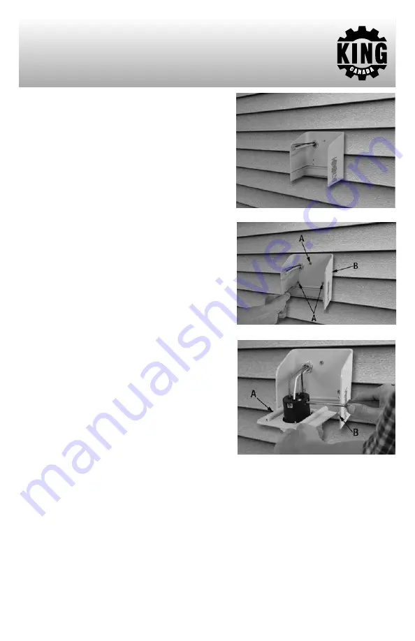
1. Using the 3 supplied screws (A) Fig.13, secure
power inlet box (B) to the outside wall by placing
3 screws into the 3 mounting holes. Do not
overtighten so much that it distorts the box.
2. Make sure the insulation gasket(s) (A) Fig.11 is
compressed enough to ensure waterproofing.
CONNECTING WIRES TO NEMA L14-30 PLUG
1. While holding the NEMA plug assembly (A)
Fig. 14, insert the 4 wires into the corresponding
screw holes.
Green wire = hole marked “G”
White wire = hole marked “W”
Red wire = hole marked “Y”
Black wire = hole marked “X”
2. Make sure the wires are pushed in completely,
then tighten the screws on the side of the Nema
plug.
3. Slide the NEMA plug assembly (A) Fig. 14 back into its track (B).
4. Tuck wires and reinstall the power inlet box cover (A) Fig.8 using the two screws
removed previously.
FIGURE 12
FIGURE 13
FIGURE 14


