background image

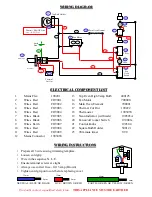
WIRING DIAGRAM 

ELECTRICAL COMPONENT LIST 


Mains Flex 

190201 

   13     Top Oven High Temp Bulb            400125 

Wires  Red 

CO9001 

   14     Fan Motor                                       700000 

Wires  Red 

CO9002 

   16     Main Oven Element                        700001 

Wires  Red 

CO9003 

   17     Thermal Cut Out                             190222 

6. 

Wires  Red 

CO9004 

   18     Thermostat                                      190303V 

7  

Wires  Black 

CO9005 

   19     Neon Indicator (with tails)              190303A 

Wires  Black 

CO9006 

   20     Fan on/off rocker Switch                 190001a 

Wires  Earth 

CO9007 

   21     Control knobs 

                     190304 

10 

Wires  Red 

CO9008 

   22     Square Bulb Holder                        500121 

11 

Wires  Red 

CO9009 

   23     90 minute timer 

                     T-90 

12

Mains Connector 

190306V 


Neutral = BLACK Line 

Live = RED Line


21 

16 

14 

Main Oven Element 

Top Bulb Holder 

Fan Motor 


Thermal 

Cut Out 

18 

19 

20 

T’Stat 

Fan 

Oven 

Switch 

Timer 

Neon 

19 

Neon 

21 

22 

L


N


17 

10 

Grommet 

Mains Flex 

Earth  
Stud 

13 

23 

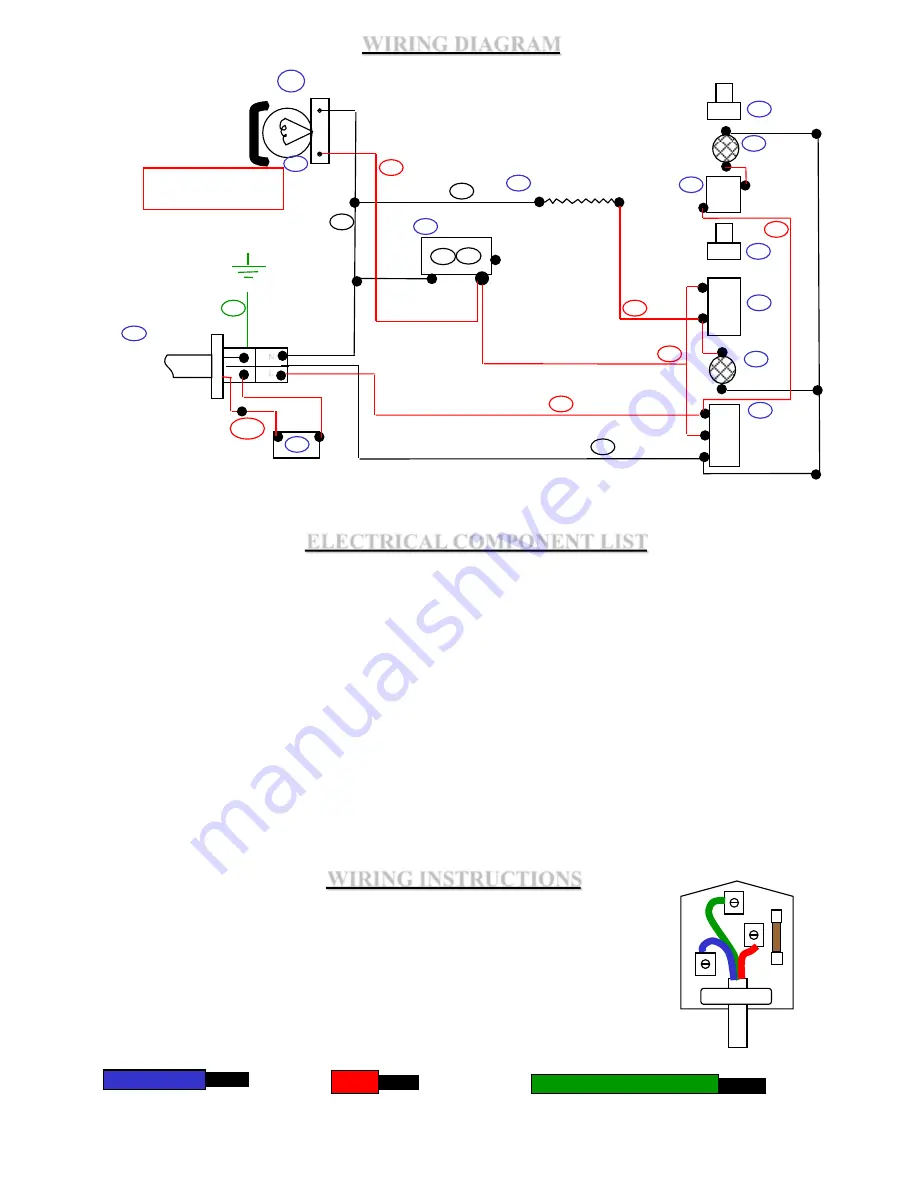
WIRING INSTRUCTIONS 

   If in doubt contact a qualified electrician.    

THIS APPLIANCE MUST BE EARTHED


• Prepare all 3 wires using trimming template 
• Loosen cord grip 
• Wire in the sequence N. L. E. 
• Ensure terminal screws are tight 
• Always use correct fuse - fit 13 amp (Brown) 
• Tighten cord grip onto cord before replacing cover 

CORD GRIP 

F

U

S

E


25mm 

8mm 

EARTH / GREEN OR YELLOW / GREEN 

40mm 

8mm 

LIVE / BROWN OR RED 

8mm 

12mm 

NEUTRAL / BLUE OR BLACK 

Summary of Contents for CLASSIC 25

Page 1: ...OPERATING INSTRUCTIONS CLASSIC 25 OVEN BEDIENUNGSANLEITUNG MODE D EMPLOI GEBRUIKSAANWIJZING PLEASE READ CAREFULLY Revised 26 03 2009 ...

Page 2: ... on the Fan on rocker switch in the control panel this will turn the fan motor on and also the display lights Turn the thermostat knob on the control panel to the temperature required For jacket potatoes we recommend 190 200 C At this stage the neon light will come on to show that the oven is heating up When the thermostat neon goes out the oven has reached temperature You can then load the prepar...

Page 3: ...s Important fibre washers must be replaced between cut out plate and oven or oven will cut out prematurely and disable cooking process Test oven at full temperature and allow to cycle several times before leaving If whole oven including lights go off cut off plate would need bending away from oven re test when cooled 5 Replacing Main Oven Fan 5 1 Remove element cover from inside oven 5 2 Unscrew c...

Page 4: ... 19001A 10 Door hinge pins top and bottom 700122 11 Front Panel Glass KEC 24 12 Display area high temp bulb 400125 13 Display area rect lamp assembly 500121 n 1 3 2 4 5 10 7 8 9 11 6 6 5 8 11 10 12 13 CHANGING THE BULB IN TOP DISPLAY AREA Disconnect Unplug the oven from the mains electricity Pull or lever off square glass bulb cover Carefully unscrew or pull out the old bulb anti clockwise and rem...

Page 5: ... it will take to cook an oven full of potatoes will depend upon a number of factors the size of potato oven temperature and even the type of potato In general however you should expect 24 x 8oz potatoes at 190 200 C for 60 minutes 18 x 10oz potatoes at 190 200 C for 70 minutes When the oven is fully loaded particularly with larger potatoes air flow inside may become restricted In this case it may ...

Page 6: ...after resetting replacing consult service engineer Top oven bulb may not be working giving the impression oven not working If all above are OK but oven still does not heat up see below OVEN NOT HEATING UP Turn oven thermostat knob to mid setting 150 200ºC in line with neon does neon light up Yes look inside oven to see if fan blade is turning Fmodels only No and fan not turning consult service eng...

Page 7: ...minute timer T 90 12 Mains Connector 190306V Neutral BLACK Line Live RED Line 3 2 21 16 7 14 7 8 Main Oven Element Top Bulb Holder Fan Motor 1 2 Thermal Cut Out 18 19 20 T Stat 1 2 3 Fan Oven Switch Timer Neon 4 2 19 Neon 21 22 9 6 L N 17 10 Grommet 1 Mains Flex Earth Stud 13 23 WIRING INSTRUCTIONS If in doubt contact a qualified electrician THIS APPLIANCE MUST BE EARTHED Prepare all 3 wires using...

Page 8: ...guarantee Please check your fuses and electricity supply before calling out an engineer as service calls requested in error will be charged at the normal rate Please have the equipment sited where it is easily accessible to the engineer and where there is adequate room to work In the case of an oven please ensure the product has not been used within 6 hours of the engineers visit and that it has c...

Reviews: